Variable impedance device for a wind turbine

a wind turbine and variable impedance technology, applied in the direction of electric generator control, process and machine control, instruments, etc., can solve the problems of increased heat dissipation, overvoltage and overcurrent, and low system stiffness

Active Publication Date: 2016-11-17
INGETEAM POWER TECH
View PDF12 Cites 34 Cited by
  • Summary
  • Abstract
  • Description
  • Claims
  • Application Information

AI Technical Summary

Benefits of technology

[0024]According to an aspect of an exemplary embodiment the wind turbine further includes a controller configur

Problems solved by technology

Thus, any topological measure which increases impedance and lowers a fault current may lower the system stiffness.
This impedance increase causes additional heat dissipation, causing a subsequent temperature rise that forces the conductor further out of the superconducting region.
Overvoltages and overcurrents may occur in the rotor windings in response to abrupt drops in grid voltage that can damage the power converter if no protection is provided.
However, the crowbar circuit 20 is costly, and bulky.
Furthermore, the current loop established between the crowbar circuit and the converter has a high inductance and is bound to produce a significant overvoltage on the crowbar IGBT terminals at turn off For that reason, the crowbar may incorporate resistance/capacitance (RC) damping networks and/or varistor devices to mitigate that overvoltage.
These circuits may be complic

Method used


Image

  • Variable impedance device for a wind turbine
  • Variable impedance device for a wind turbine
  • Variable impedance device for a wind turbine

Examples


embodiment 1

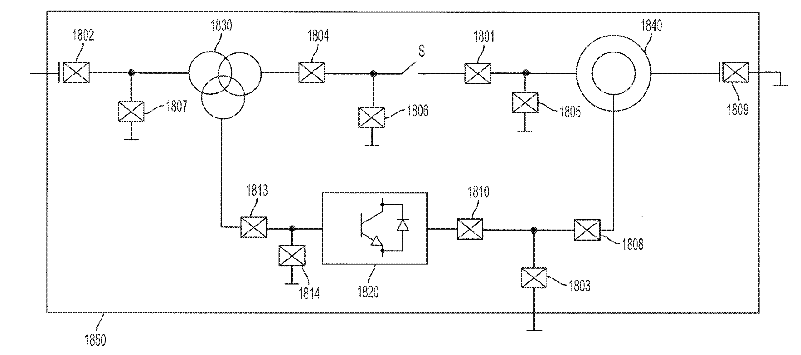
[0105 is directed to a wind turbine including a housing; an asynchronous generator disposed in the housing and configured to be electrically connected to a power grid connection; a power converter circuit disposed in the housing and configured to be electrically connected to the asynchronous generator; and a variable impedance device disposed in the housing, connected to the generator and configured to limit current by varying impedance in response to a transient current.

[0106]Embodiment 2 is directed to the wind turbine of embodiment 1, wherein the variable impedance device is arranged in series between the asynchronous generator and the power grid connection.

[0107]Embodiment 3 is directed to the wind turbine of embodiment 2, further comprising a fixed impedance device connected in parallel with the variable impedance device.

[0108]Embodiment 4 is directed to the wind turbine of embodiment 3, wherein the variable impedance device is a variable inductor.

[0109]Embodiment 5 is directed...

embodiment 8

[0113]Embodiment 9 is directed to the wind turbine of embodiment 8, wherein the fixed impedance device is a resistor

embodiment 10

[0114 is directed to the wind turbine according to embodiments 1-9, further comprising a controller configured to control the variable impedance device in response to detection of the transient current to vary impedance.


PUM


Abstract

A wind turbine that includes a housing, an asynchronous generator disposed in the housing and configured to be electrically connected to a power grid connection; a power converter circuit disposed in the housing and configured to be electrically connected to the asynchronous generator; and a variable impedance device disposed in the housing, connected to the generator and configured to limit current by varying impedance in response to a transient current. The wind turbine delivers reactive power to the power grid when the variable impedance device varies impedance in response to the transient current. The variable impedance device can be arranged in series between the asynchronous generator and the power grid connection, or can be in a shunt arrangement between the asynchronous generator and a neural point.

Description

CROSS-REFERENCE TO RELATED APPLICATION[0001]This application claims the benefit of U.S. Provisional Patent Application No. 61 / 917,538 filed on Dec. 18, 2013 in the U.S. Patent and Trademark Office, the disclosure of which is incorporated herein by reference in its entirety.BACKGROUND[0002]1. Technical Field[0003]Apparatuses and methods consistent with exemplary embodiments relate to the use of variable impedance devices, for example Fault Current Limiter (FCL) devices, and variable impedance networks in wind turbine systems, to mitigate the effects caused by power grid disturbances such as voltage dips. Certain embodiments are configured to facilitate compliance with grid codes that are imposed upon such systems.[0004]2. Background Art[0005]Variable impedance devices, such as FCL devices, have recently been developed that can mitigate the increasing fault current levels during transmission and distribution in electrical power networks. Some of these developments have been accompanie...

Claims


Application Information

Patent Timeline
IPC IPC(8): F03D9/00G05F5/00F03D9/25
CPCF03D9/003G05F5/00F03D9/25H02H7/06H02P9/102H02P9/007H02P9/16H02J3/1807H02J3/1835Y02E40/30F03D9/255H02J2300/28H02J3/381Y02E10/72Y02E10/76H02J3/50
Inventor ZABALZA, FRANCISCO JAVIER CHIVITEREMIREZ, CARLOS GIRONESMAYOR, AINHOA CARCAROREGI, ENEKO OLEATABERNA, JESUS LOPEZ
Owner INGETEAM POWER TECH
Why Eureka
Try Eureka