Centrifugal force pendulum

Inactive Publication Date: 2016-11-17
SCHAEFFLER TECH AG & CO KG
View PDF0 Cites 17 Cited by
  • Summary
  • Abstract
  • Description
  • Claims
  • Application Information

AI Technical Summary

Benefits of technology

[0007]In another embodiment, the first clamping element has a first longitudinal end in contact with a longitudinal end of the cutout. A second longitudinal end of the first clamping element is in contact with the means of guidance. The first clamping element is preferably positioned radially to the inside of the means of guidance. This makes it possible to guarantee that the first clamping element may be designed, for example, as a coil spring, in particular as a compression spring, and thus that an especially cost-effective centrifugal pendulum can be provided.
[0008]In another embodiment, the means of guidance has a connecting pin and a guide element, the connecting pin being connected to the additional pendulum mass or to the first pendulum mass part. The guide element has a receptacle which is engaged by the connecting pin. The cutout has a cutout contour. The guide element has on its outer surface at least one guide surface facing the cutout contour. The guide surface is at least partially in contact with the cutout contour, in order to guide the connecting pin in the cutout. The receptacle is preferably of rectilinear design and/or is oriented essentially tangentially relative to the axis of rotation. In this way, noises of coupling the additional pendulum mass part with the first pendulum mass part can be avoided.
[0009]In another embodiment, a second clamping element is provided in the receptacle, the s

Problems solved by technology

This results in an increase in the total mass of the centrifugal pendulum.
Furthermor

Method used


Image

  • Centrifugal force pendulum
  • Centrifugal force pendulum
  • Centrifugal force pendulum

Examples


first embodiment

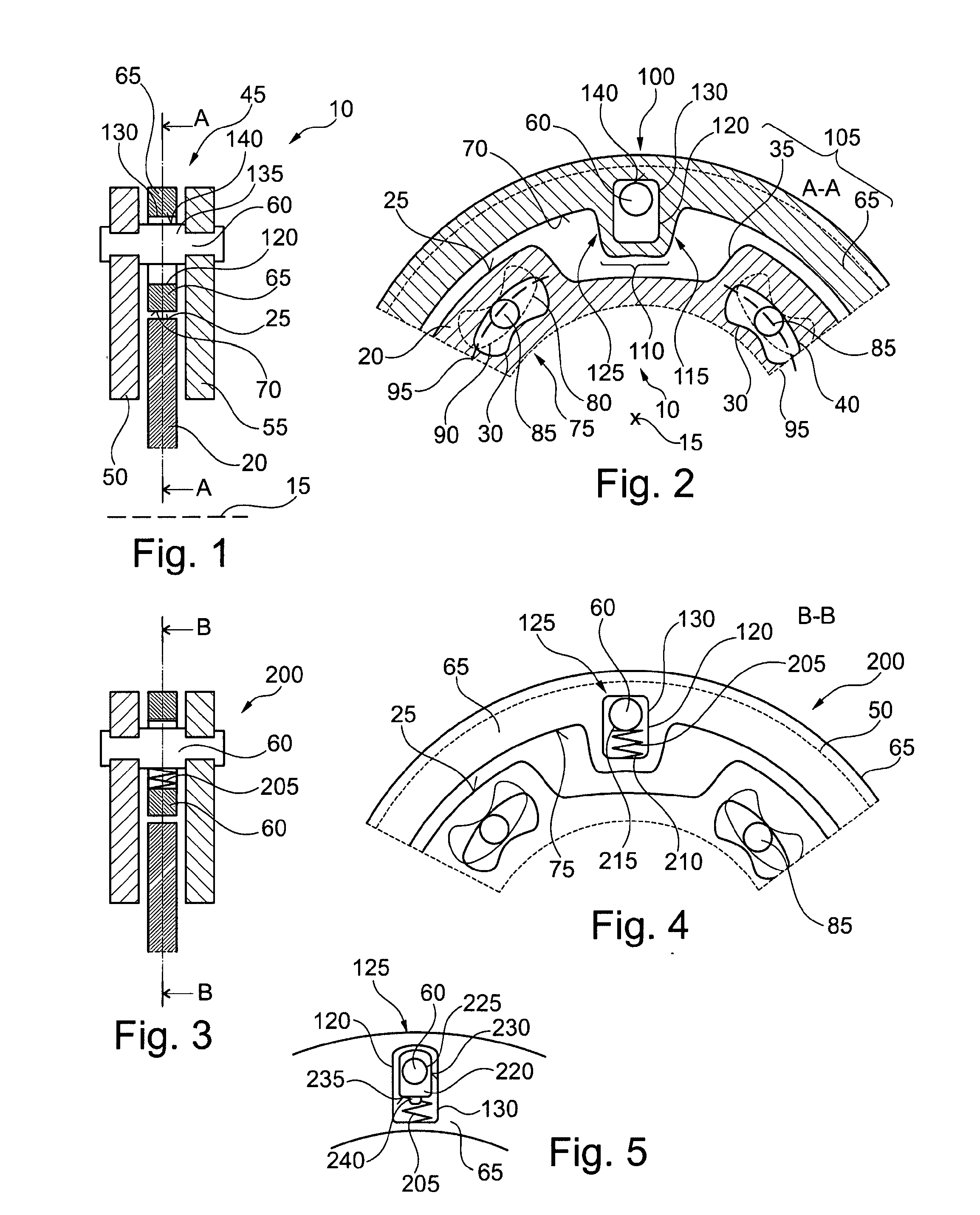
[0023]FIG. 1 shows a semi-longitudinal section through a centrifugal pendulum 10 ; FIG. 2 shows a cross section along a sectional plane A-A shown in FIG. 1, through the centrifugal pendulum 10 shown in FIG. 1.

[0024]The centrifugal pendulum 10 is mounted so that it can rotate around an axis of rotation 15. The centrifugal pendulum 10 can be used here, for example, in a drivetrain of a motor vehicle, in particular in a torque transfer device and / or a torsional vibration damper. The centrifugal pendulum 10 includes a pendulum flange 20. In this case, the pendulum flange 20 extends essentially from radially inside to radially outside, perpendicular to the axis of rotation 15. The pendulum flange 20 has a bearing surface 25 on an outer circumferential surface, radially on the outside. Furthermore, the pendulum flange 20 has a first cutout 30 and a second cutout 35. The second cutout 35 is open radially toward the outside, while the first cutout is kidney-shaped and has a closed first cut...

second embodiment

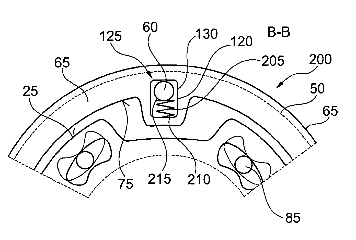
[0031]FIG. 3 shows a semi-longitudinal section through a centrifugal pendulum 200 according to a FIG. 4 shows a detail of a cross section of the centrifugal pendulum 200 shown in FIG. 3, along a sectional plane B-B.

[0032]The centrifugal pendulum 200 is essentially identical in design to the centrifugal pendulum 10 shown in FIGS. 1 and 2. Differing from it, the centrifugal pendulum 200 has a first clamping element 205, which is positioned in the fourth cutout 120 of the second sliding block guide 115. In this case, the clamping element 205 is positioned axially between the first pendulum mass part 50 and the second pendulum mass part 55, radially to the outside of the pendulum flange 20. The first clamping element 205 is designed here as a coil spring. Other spring designs are of course also conceivable. The first clamping element 205 is braced at a first longitudinal end 210 radially to the inside of the third cutout contour 130 of the fourth cutout 120. A second longitudinal end 2...

third embodiment

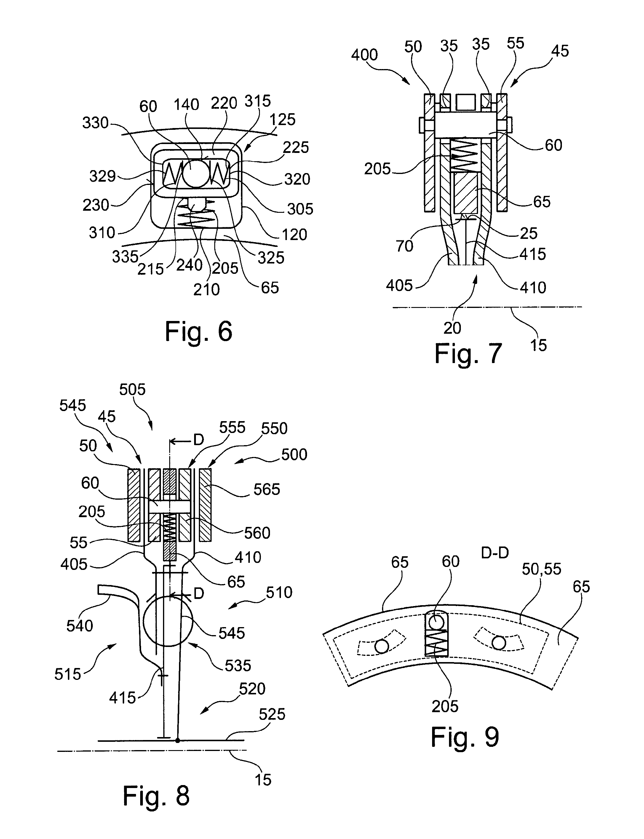
[0039]FIG. 7 shows a semi-longitudinal section through a centrifugal pendulum 400 according to a The centrifugal pendulum 400 is similar in design to the centrifugal pendulum 200 shown in FIGS. 3 and 4. Differing therefrom, the pendulum flange 20 has a first pendulum flange part 405 and a second pendulum flange part 410. The first and second pendulum flange parts 405, 410 are passed radially from inside to outside adjacent to the pendulum mass parts 50, 55, essentially perpendicular to the axis of rotation 15. The first pendulum mass part 50 is positioned to the left side of the first pendulum flange part 405 and the second pendulum mass part 55 is positioned to the right side of the second pendulum flange part 410. The additional pendulum mass part 65 is positioned between the pendulum flange parts 405, 410 in the axial direction. The connecting pin 60 extends in the axial direction parallel to the axis of rotation 15 and connects the first pendulum mass part 50 to the second pend...


PUM


Abstract

A centrifugal pendulum for a drivetrain of a motor vehicle, which is mountable rotatably around an axis of rotation, having a pendulum mass, a first sliding block guide and a pendulum flange, where the pendulum mass includes a first pendulum mass part, where the first pendulum mass part is coupled with the pendulum flange via the first sliding block guide, where the first sliding block guide is designed to guide the first pendulum mass part along an oscillation path in an oscillating motion, where the pendulum mass has an additional pendulum mass part and a coupling, where the additional pendulum mass part is coupled with the first pendulum mass part by the coupling so that it is movable at least in the radial direction relative to the pendulum mass part.

Description

BACKGROUND[0001]Centrifugal pendulums having a pendulum flange and a pendulum mass are known. The pendulum mass is coupled with the pendulum flange by means of a sliding block guide. The sliding block guide establishes an oscillation path for the pendulum mass, along which the pendulum mass oscillates when torsional vibrations are introduced into the centrifugal pendulum. The return force to relocate the deflected pendulum mass back to a rest position again is dependent on a speed of rotation of the centrifugal pendulum and the mass of the pendulum mass. Usually, when designing centrifugal pendulums, the mass of the pendulum masses is increased to increase the return force at a predefined rotation speed. This results in an increase in the total mass of the centrifugal pendulum. Furthermore, additional construction space is needed to accommodate the enlarged pendulum mass.SUMMARY OF THE INVENTION[0002]It is an object of the present invention to provide an improved centrifugal pendulu...

Claims


Application Information

Patent Timeline
IPC IPC(8): F16F15/14
CPCF16F15/145
Inventor DINGER, CHRISTIAN
Owner SCHAEFFLER TECH AG & CO KG
Why Eureka
Try Eureka