Load Transducer and Force Measurement Assembly Using the Same

a technology of load transducer and force measurement assembly, which is applied in the direction of force measurement, force/torque/work measurement apparatus, instruments, etc., can solve the problems of significant increase in material costs associated with the fabrication of force plates, and elongation of load transducers that utilize an excessive amount of stock materials, so as to facilitate visualization and clear understanding

Active Publication Date: 2016-11-17
BERTEC
View PDF8 Cites 57 Cited by
  • Summary
  • Abstract
  • Description
  • Claims
  • Application Information

AI Technical Summary

Benefits of technology

[0090]It should be understood that the appended drawings are not necessarily to scale, presenting a somewhat simplified representation of various preferred features illustrative of the basic principles of the invention. The specific design features of the load transducers as disclosed herein, including, for example, specific dimensions, orientations, locations, and shapes of the various components, will be determined in part by the particular intended application and use environment. Certain features of the illustrated embodiments have been enlarged or distorted relative to others to facilitate visualization and clear understanding. In particular, thin features may be thickened, for example, for clarity or illustration. All references to direction and position, unless otherwise indicated, refer to the orientation of the load transducers illustrated in the drawings. In general, up or upward generally refers to an upward direction within the plane of the paper in FIG. 1 and down or downward generally refers to a downward direction within the plane of the paper in FIG. 1.

Problems solved by technology

These custom load transducers significantly increase the material costs associated with the fabrication of a force plate.
Also, conventional load transducers often span the full length or width of the force plate component to which they are mounted, thereby resulting in elongate load transducers that utilize an excessive amount of stock material.

Method used


Image

  • Load Transducer and Force Measurement Assembly Using the Same
  • Load Transducer and Force Measurement Assembly Using the Same
  • Load Transducer and Force Measurement Assembly Using the Same

Examples


first embodiment

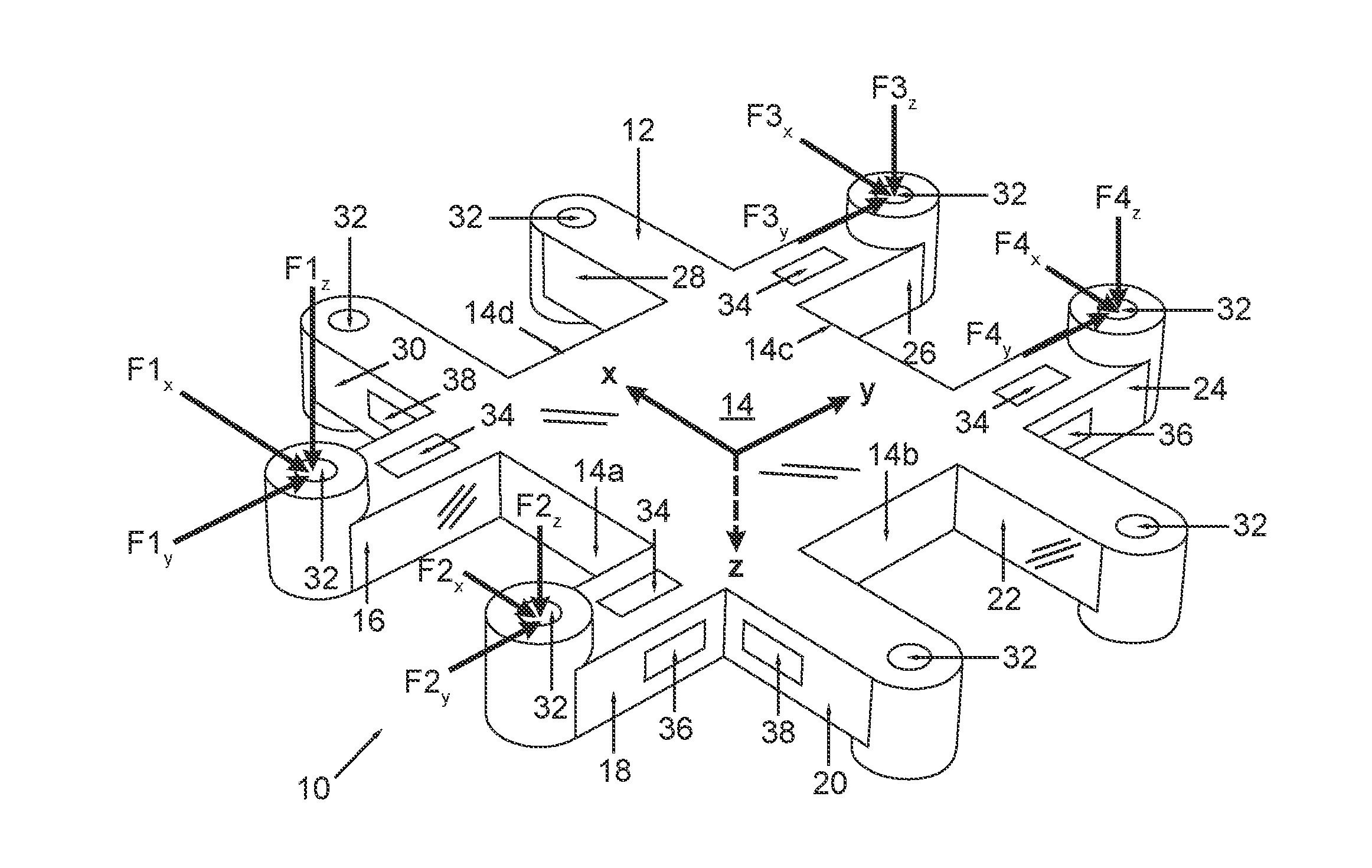
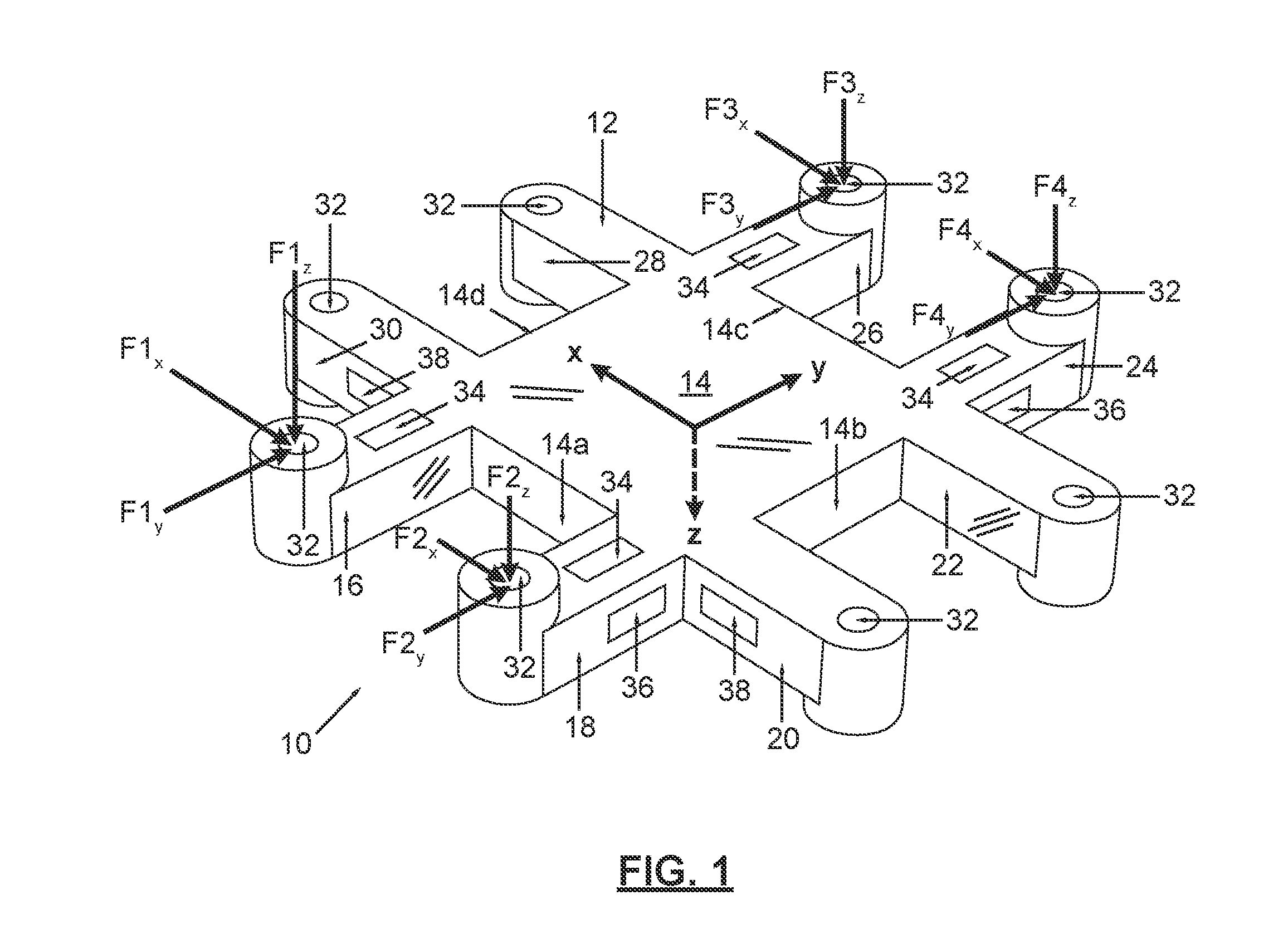
[0036]FIG. 1 is a perspective view of a low profile load transducer, according to the invention;

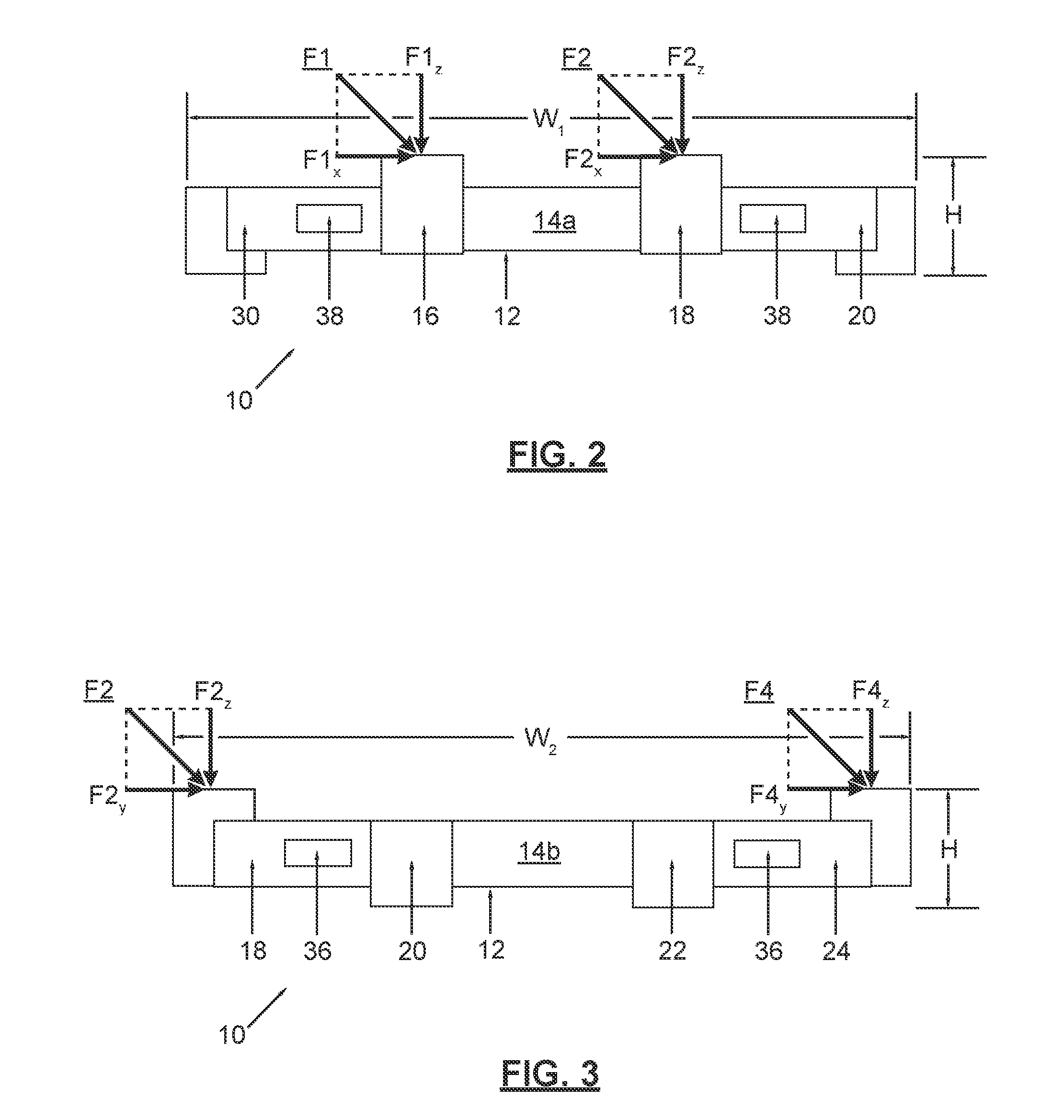
[0037]FIG. 2 is a first side view of the low profile load transducer of FIG. 1, according to the first embodiment of the invention;

[0038]FIG. 3 is a second side view of the low profile load transducer of FIG. 1, according to the first embodiment of the invention;

[0039]FIG. 4 is a top view of the low profile load transducer of FIG. 1, according to the first embodiment of the invention;

[0040]FIG. 5 is a block diagram illustrating data manipulation operations carried out by the load transducer data processing system, according to an embodiment of the invention;

second embodiment

[0041]FIG. 6 is a perspective view of a low profile load transducer, according to the invention;

[0042]FIG. 7 is a first side view of the low profile load transducer of FIG. 6, according to the second embodiment of the invention;

[0043]FIG. 8 is a second side view of the low profile load transducer of FIG. 6, according to the second embodiment of the invention;

[0044]FIG. 9 is a top view of the low profile load transducer of FIG. 6, according to the second embodiment of the invention;

third embodiment

[0045]FIG. 10 is a perspective view of a low profile load transducer, according to the invention;

[0046]FIG. 11 is a first side view of the low profile load transducer of FIG. 10, according to the third embodiment of the invention;

[0047]FIG. 12 is a second side view of the low profile load transducer of FIG. 10, according to the third embodiment of the invention;

[0048]FIG. 13 is a top view of the low profile load transducer of FIG. 10, according to the third embodiment of the invention;

[0049]FIG. 14 is a bottom view of the low profile load transducer of FIG. 10, according to the third embodiment of the invention;


PUM

PropertyMeasurementUnit
forceaaaaaaaaaa
shear forceaaaaaaaaaa
sizeaaaaaaaaaa

Abstract

A load transducer is disclosed herein. The load transducer includes a body portion having a plurality of sides, the plurality of sides of the body portion including a first side; a plurality of beam portions including a first beam portion and a second beam portion, the first beam portion being coupled to the body portion, the second beam portion being coupled to the first beam portion, and the second beam portion extending along the first side of the body portion; and at least one load cell disposed on one or more of the plurality of beam portions, the at least one load cell configured to measure at least one force or moment component of a load applied to the load transducer. A force measurement assembly including a plurality of load transducers with first and second beam portions is also disclosed herein.

Description

CROSS-REFERENCE TO RELATED APPLICATIONS[0001]This is a continuation-in-part of U.S. Nonprovisional patent application Ser. No. 14 / 714,797, entitled “Load Transducer and Force Measurement Assembly Using the Same”, filed on May 18, 2015; which is a continuation-in-part of U.S. Nonprovisional patent application Ser. No. 14 / 158,809, entitled “Low Profile Load Transducer”, filed on Jan. 18, 2014, now U.S. Pat. No. 9,032,817; and further claims the benefit of U.S. Provisional Patent Application No. 61 / 887,357, entitled “Low Profile Load Transducer”, filed on Oct. 5, 2013, the disclosure of each of which is hereby incorporated by reference as if set forth in their entirety herein.STATEMENT REGARDING FEDERALLY SPONSORED RESEARCH OR DEVELOPMENT[0002]Not Applicable.NAMES OF THE PARTIES TO A JOINT RESEARCH AGREEMENT[0003]Not Applicable.INCORPORATION BY REFERENCE OF MATERIAL SUBMITTED ON A COMPACT DISK[0004]Not Applicable.BACKGROUND OF THE INVENTION[0005]1. Field of the Invention[0006]The field...

Claims


Application Information

Patent Timeline
Patent Type & Authority Applications(United States)
IPC IPC(8): G01L1/22G01L5/16G01N3/24
CPCG01L1/2206G01L5/161G01N3/24G01L5/162G01L5/1627
Inventor BERME, NECIPHOFFMAN, BENJAMIN ROBERT
Owner BERTEC
Why Eureka
Try Eureka