Control device for internal combustion engine

a control device and internal combustion engine technology, applied in the direction of electric control, corrosion prevention fuel injection, instruments, etc., can solve the problems of corroding of the injection aperture located at the nozzle tip portion of the nozzle, and achieve the effect of reducing the computation load

Active Publication Date: 2016-11-17
TOYOTA JIDOSHA KK
View PDF1 Cites 3 Cited by
  • Summary
  • Abstract
  • Description
  • Claims
  • Application Information

AI Technical Summary

Benefits of technology

[0014]The control device for an internal combustion engine disclosed in the present description maintains the accuracy in the determination of whether the injection aperture located at the nozzle tip portion is to corrode and reduces the computation load in the determination.

Problems solved by technology

It has been conventionally known that an injection aperture located at a nozzle tip portion may corrode due to the adhesion of condensed water formed by dew condensation of water on the nozzle tip portion of an injector that injects fuel into a cylinder of an internal combustion engine.

Method used


Image

  • Control device for internal combustion engine
  • Control device for internal combustion engine
  • Control device for internal combustion engine

Examples


first embodiment

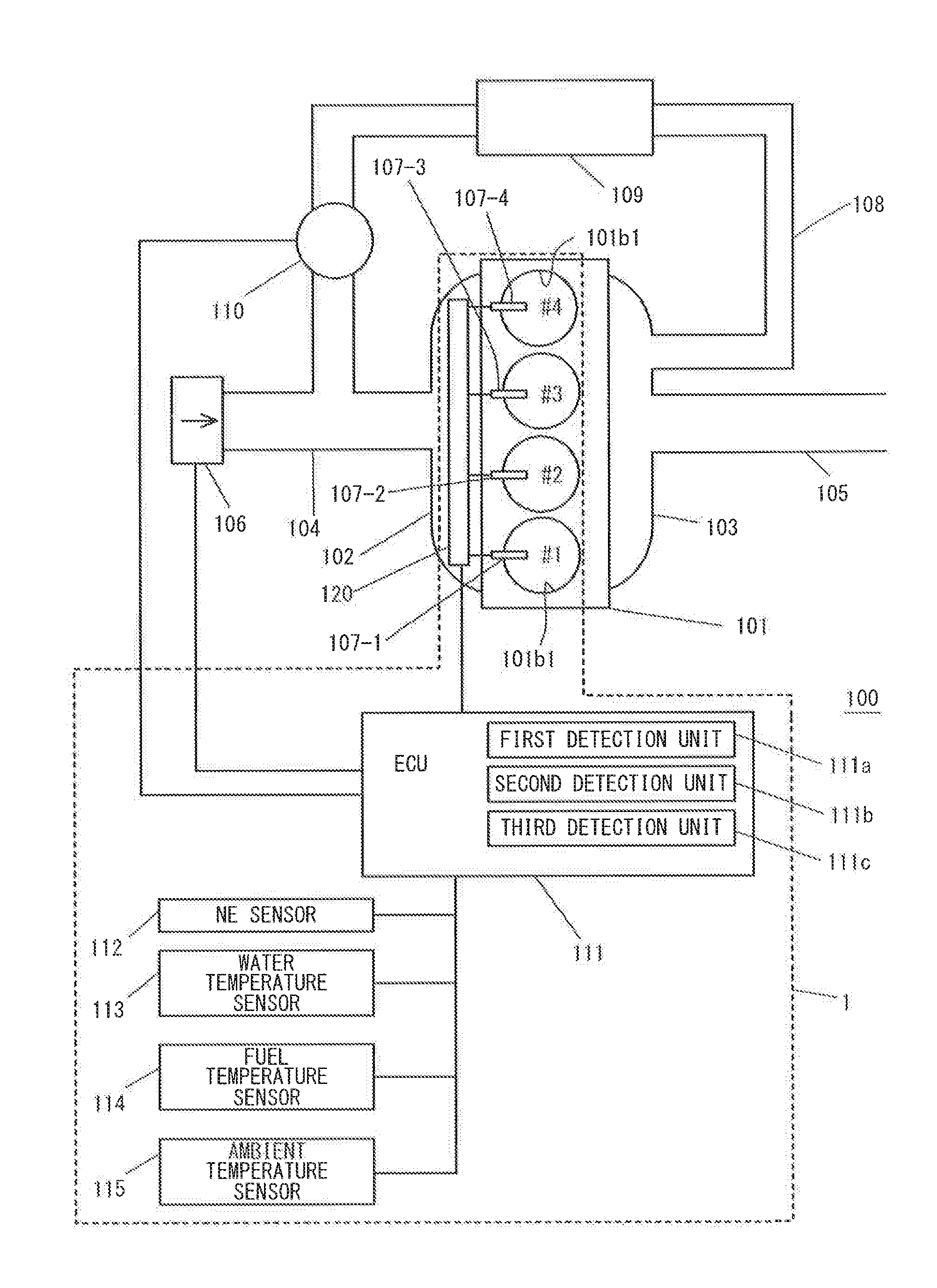
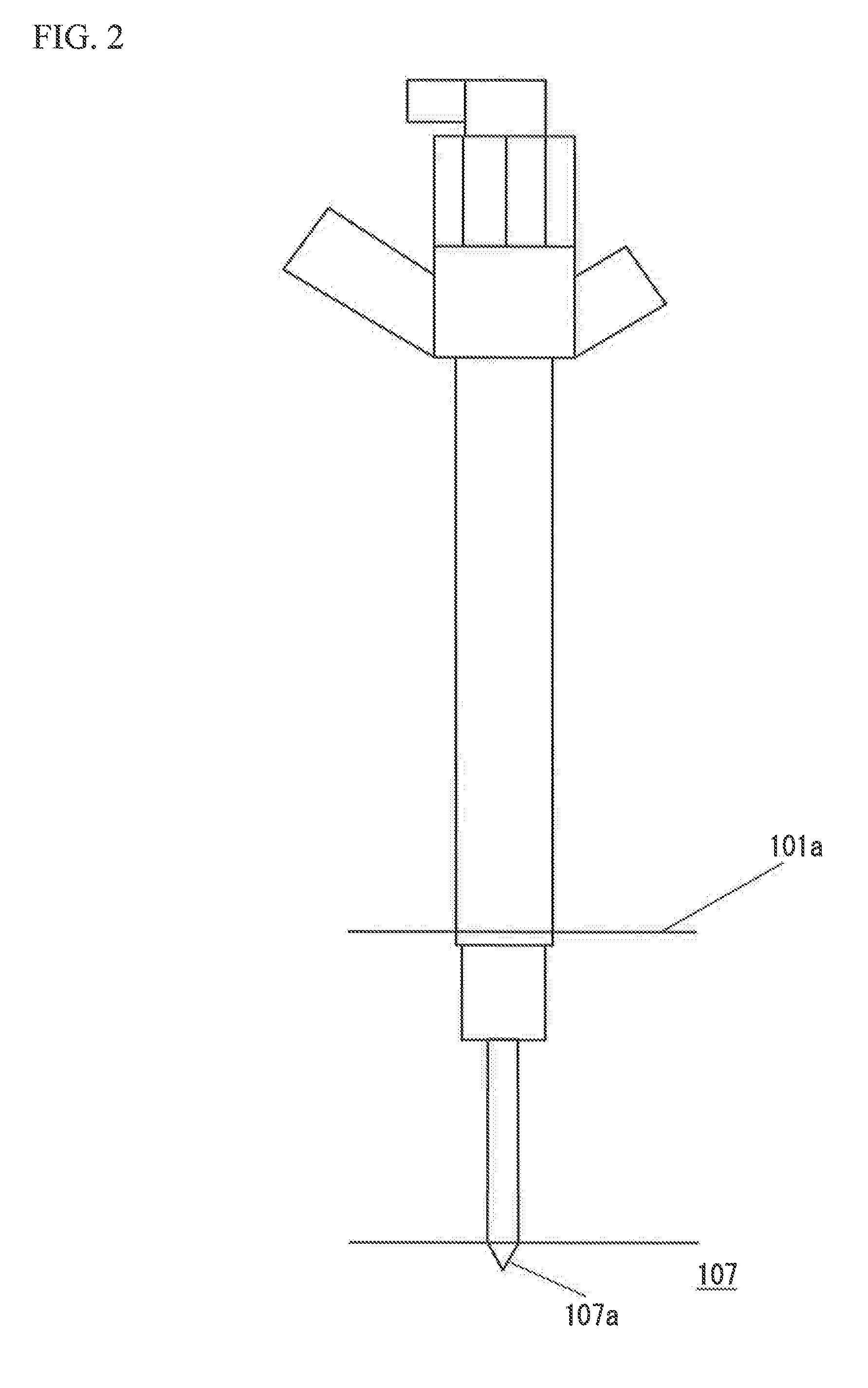
[0033]FIG. 1 is an explanatory diagram illustrating an overview configuration of an internal combustion engine 100 of a first embodiment. FIG. 2 is an explanatory diagram of an injector 107 installed in the internal combustion engine 100. A fuel injection device 1 is installed in the internal combustion engine 100. The internal combustion engine 100 in the first embodiment is an internal combustion engine that injects fuel into cylinders, more specifically, is a diesel internal combustion engine, but may be a gasoline internal combustion engine. Although the number of the cylinders of the internal combustion engine is not limited, the internal combustion engine 100 of the present embodiment has four cylinders. The internal combustion engine 100 includes an engine body 101 including a cylinder head 101a and a cylinder block 101b, and a #1 cylinder through a #4 cylinder in the engine body 101. The fuel injection device 1 includes a #1 injector 107-1 through a #4 injector 107-4 respect...

second embodiment

[0057]Next, a second embodiment will be described with reference to FIG. 10A, FIG. 10B, and FIG. 10C. The second embodiment replaces the method of determining whether dew condensation is to occur in the first embodiment with an alternative method. That is to say, the second embodiment changes the process at step S6 in the flowchart illustrated in FIG. 4.

[0058]FIG. 10A, FIG. 10B, and FIG. 10C are diagrams for describing a method of determining whether dew condensation is to occur. FIG. 10A is a base map illustrating the decrease history of the temperature of the nozzle tip after shutdown of the internal combustion engine. FIG. 10B is a graph predicting a process of how the temperature of the nozzle tip changes with time by using the base map based on the temperature of cooling water converted from the head heat quantity. FIG. 10C illustrate a map used to calculate the dew point arrival time.

[0059]The ECU 111 includes a base map illustrated in FIG. 10A. The base map illustrates a rela...

third embodiment

[0060]Next, the third embodiment will be described with reference to FIG. 11 through FIG. 13. The third embodiment replaces the estimation method of the head heat quantity Q in the first embodiment with an alternative method. That is to say, the process at step S3 in the flowchart illustrated in FIG. 4 is changed.

[0061]With reference to FIG. 12, an internal combustion engine 200 includes a first water temperature sensor 113a at the front end side of the cylinder head 101a, and a second water temperature sensor 113b at the rear end side. With reference to FIG. 11, at step S12a, a temperature Tw1 of cooling water at the upstream side is detected by the first water temperature sensor 113a. At step S12b, a temperature Tw2 of cooling water at the downstream side is detected by the second water temperature sensor 113b. At step S12c, a temperature difference ΔT between the upstream and downstream temperatures is calculated. In the example illustrated in FIG. 12, the temperature difference ...


PUM


Abstract

A control device for an internal combustion engine that includes: a first detection unit detecting, as a first parameter, a temperature of a nozzle tip of an injector; and a second detection unit detecting, as a second parameter, a heat quantity of a cylinder head, and executes a dew condensation determination by using at least one of the first parameter and the second parameter, the control device includes: a third detection unit detecting an evaluation value allowing to evaluate a state of the internal combustion engine, a threshold value for selecting which parameter of the first and second parameters is selected being set with respect to the evaluation value, wherein the control device switches a parameter to be used to the first parameter, to the second parameter, or to both the first and second parameters in accordance with the evaluation value when executing the dew condensation determination.

Description

CROSS-REFERENCE TO RELATED APPLICATIONS[0001]This application is a national phase application of International Application No. PCT / JP2014 / 082713, filed Dec. 10, 2014, and claims the priority of Japanese Application No. 2013-260668, filed Dec. 17, 2013, the content of both of which is incorporated herein by reference.TECHNICAL FIELD[0002]The present invention relates to a control device for an internal combustion engine.BACKGROUND ART[0003]It has been conventionally known that an injection aperture located at a nozzle tip portion may corrode due to the adhesion of condensed water formed by dew condensation of water on the nozzle tip portion of an injector that injects fuel into a cylinder of an internal combustion engine. Whether dew condensation forms on the nozzle tip portion is affected by the relation between the temperature of the nozzle tip and a dew point of the atmosphere in the cylinder. From this perspective, Patent Document 1 suggests estimating the temperature of the nozz...

Claims


Application Information

Patent Timeline
Patent Type & Authority Applications(United States)
IPC IPC(8): G01M15/04F01P3/20F01P11/16F02M61/18
CPCG01M15/048F02M61/18F01P2025/08F01P11/16F01P3/20F02D41/042F02D2200/021F02M2200/05F02D2200/0414F02D2200/0418
Inventor IKEMOTO, MASATO
Owner TOYOTA JIDOSHA KK
Why Eureka
Try Eureka