

Electromagnetic Wave Detection Apparatus
a detection apparatus and electromagnetic wave technology, applied in the direction of electromagentic field characteristics, measurement devices, instruments, etc., can solve the problem that the surveillance needs to be performed quickly on si
- Summary
- Abstract
- Description
- Claims
- Application Information
AI Technical Summary
Benefits of technology
Problems solved by technology
Method used
Image

Examples
embodiment 1
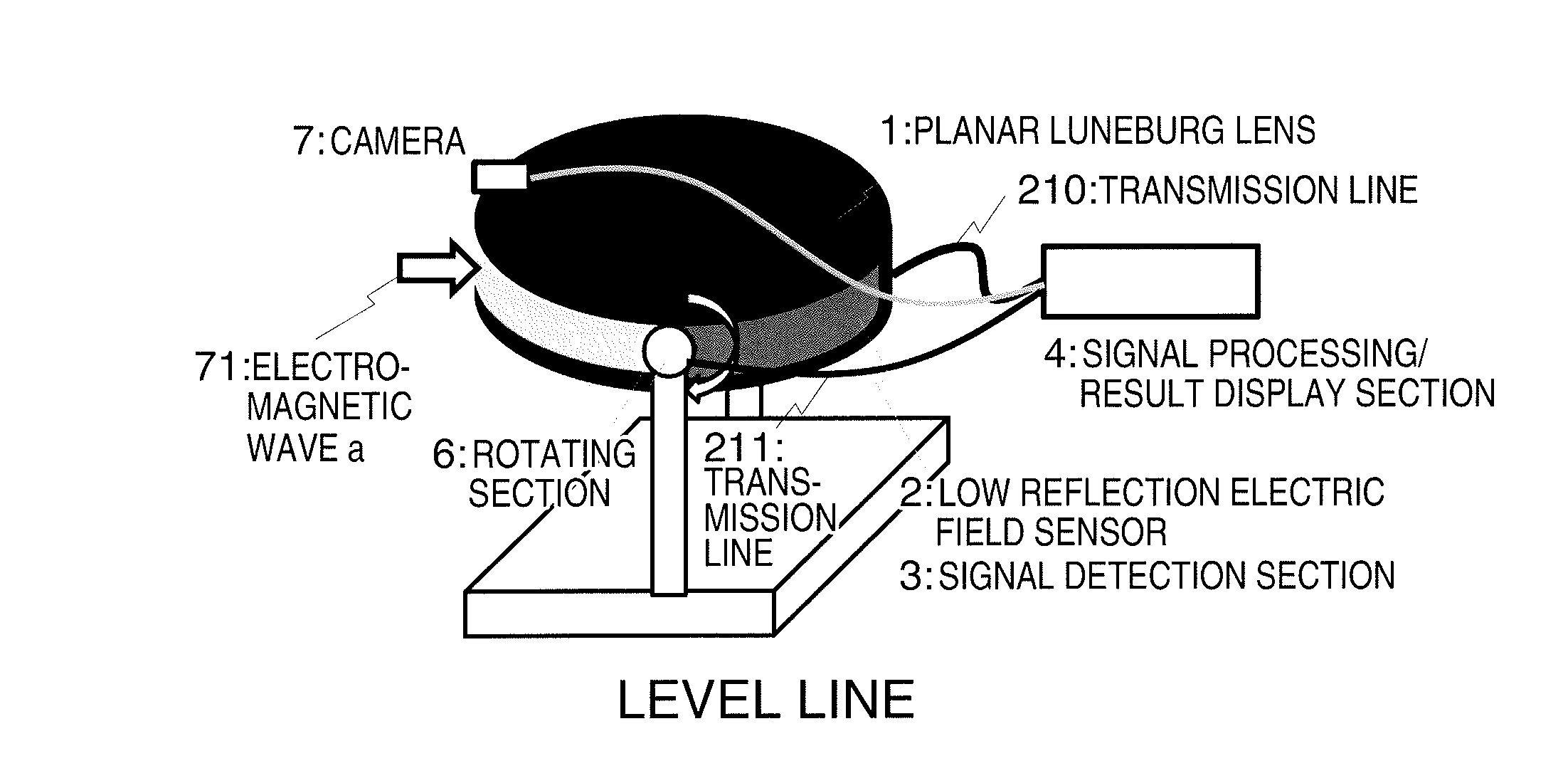
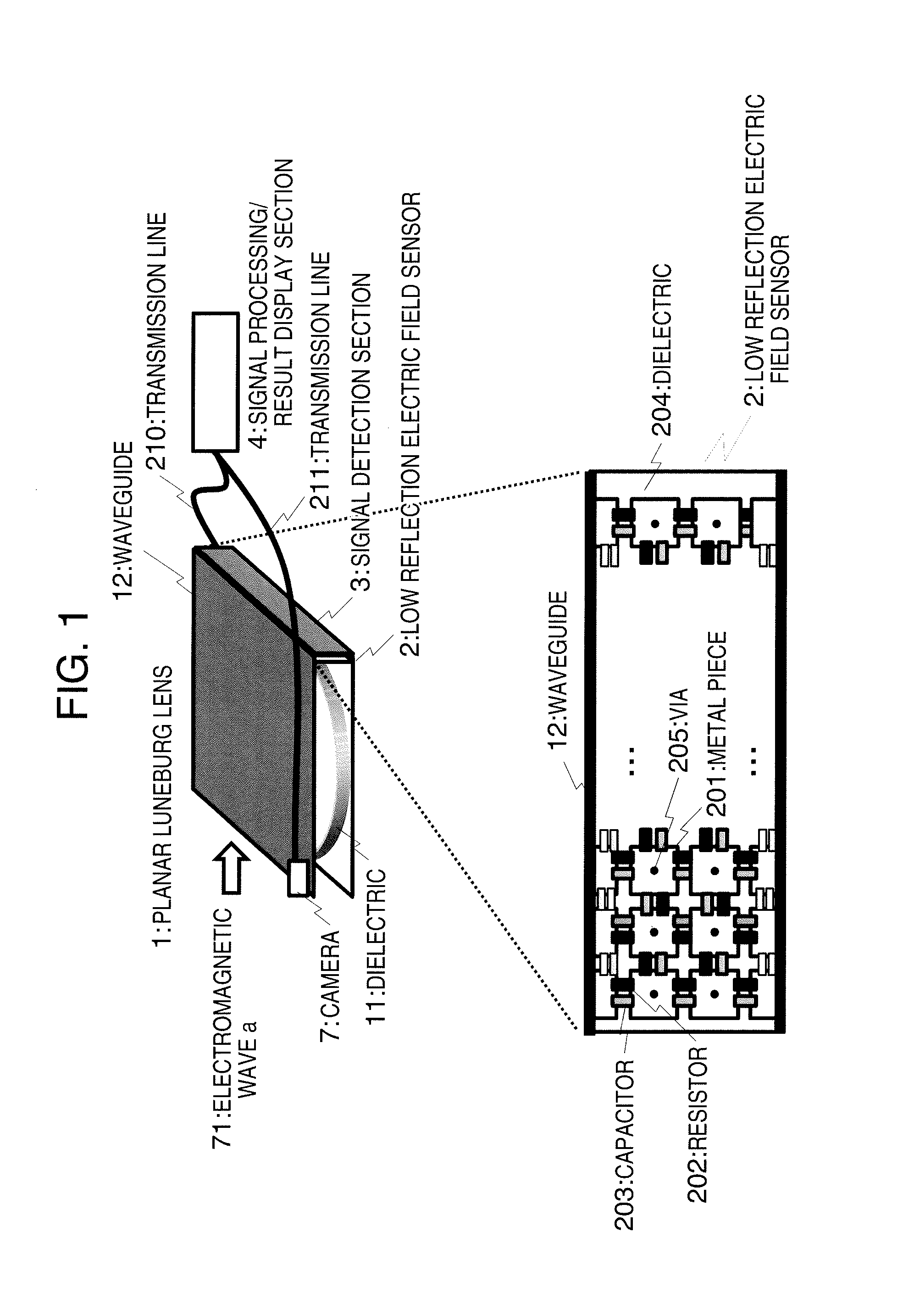
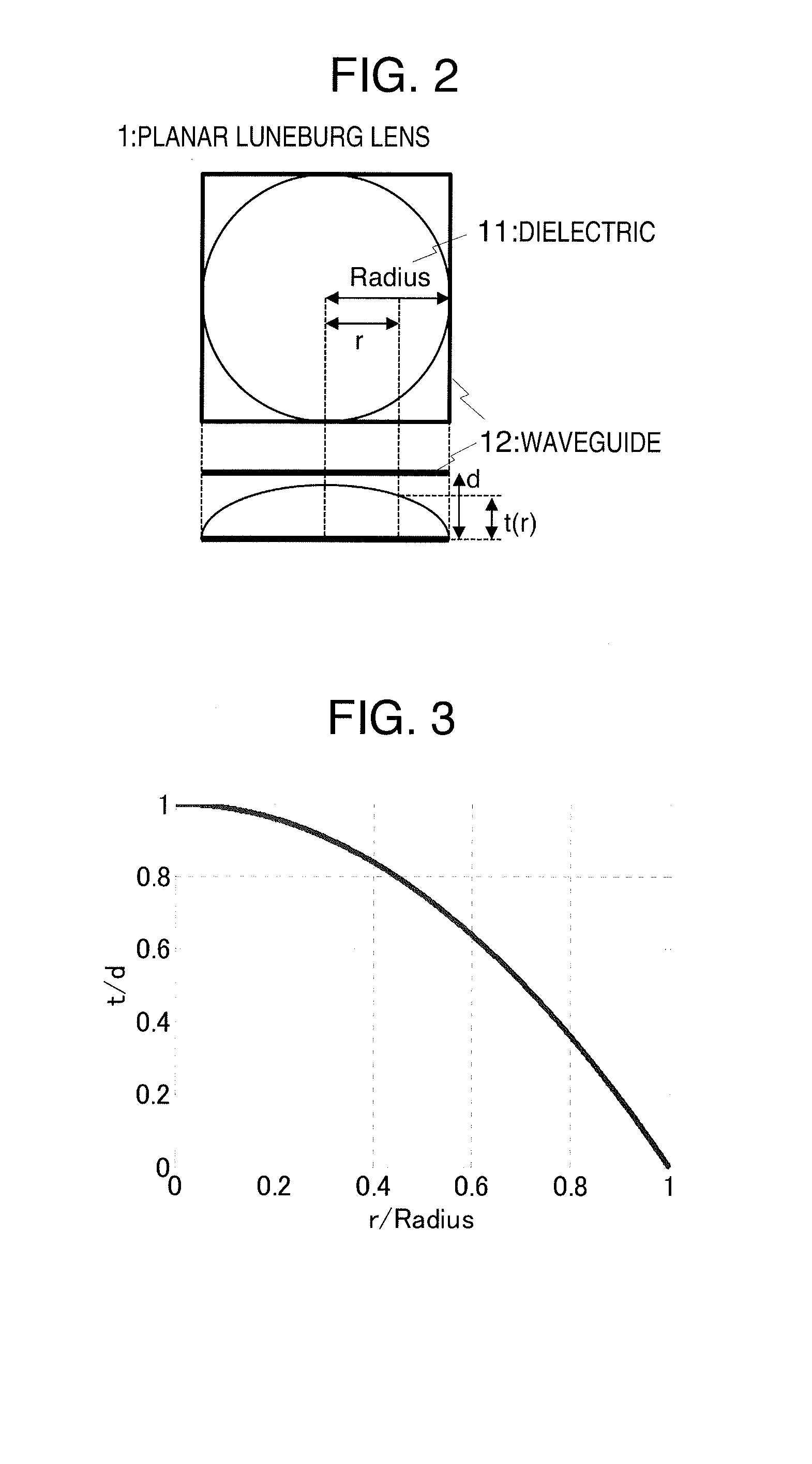
[0043]In Embodiment 1, a configuration of an electromagnetic wave detection apparatus provided with a configuration for visualizing electromagnetic waves will be described with reference to FIG. 1 to FIG. 13. FIG. 1 is a view showing a configuration of an electromagnetic wave detection apparatus according to the present embodiment. FIG. 2 shows a two-dimensional Luneburg lens of an direction of arrival separation section of the electromagnetic wave detection apparatus according to the present embodiment. FIG. 3 is a view showing the thickness of a dielectric of the Luneburg lens according to the present embodiment. FIG. 4 shows an example of electromagnetic field analysis of radio wave propagation characteristics of the Luneburg lens according to the present embodiment. FIG. 5 shows an example of an ideal configuration of an electric field sensor according to the present embodiment. FIG. 6 shows a partial overhead view of the electric field sensor according to the present embodiment...
embodiment 2
[0073]FIG. 14 shows a second embodiment of the present invention. In the first embodiment, the waveguide type electric field sensor is provided on the plane perpendicular to the incident angle of 0 degree of the lens, but in the present embodiment, an electric field sensor is provided along the shape of the lens.
[0074]In the present embodiment, the sensor is provided along the shape of the lens shape so as to cover the half peripheral surface of the lens. In Embodiment 1, it is estimated that the energy of electromagnetic waves detected by the sensor arranged at a position separated from the lens surface is reduced as compared with the energy of electromagnetic waves detected by the sensor arranged on the lens surface. However, when the sensor is arranged at each of the focal points of the lens, the sensor can receive the greatest energy of electromagnetic waves, and hence the detection sensitivity can be improved. The lateral length of the sensor may be arbitrarily set.
embodiment 3
[0075]A third embodiment of the present invention will be described with reference to FIG. 15 to FIG. 17. FIG. 15 shows a waveguide type electric field sensor according to the third embodiment of the present invention. FIG. 15 is an overhead view of the waveguide type electric field sensor, which is configured such that metal waveguide 12 of the plane Luneburg lens is positioned at the center between the metal pieces arranged in the periodic structure.
[0076]The periodic structure metal pieces act as if there are electrically folded periodic structures due to electric image. FIG. 16 shows the equivalent circuit of the portion represented by dotted lines c and including the electric image of the portion in contact with waveguide 12. When end portion resistor 212 and end portion capacitor 213 are respectively set as R″ and Cadd″, it can be seem, by the electric image, such that each of a pair of portion resistors 212 of R″ and a pair of portion capacitors 213 of Cadd″ are arranged in s...
PUM
 Abstract
Description
Claims
Application Information