Power transmission device and power reception device

a technology of power transmission device and power reception device, which is applied in the direction of instruments, transportation and packaging, and using reradiation, etc., can solve the problem of inability to detect a relatively small foreign object compared to the power feeding coil

Active Publication Date: 2018-05-29
TOYOTA JIDOSHA KK +2
View PDF89 Cites 1 Cited by
  • Summary
  • Abstract
  • Description
  • Claims
  • Application Information

AI Technical Summary

Benefits of technology

[0008]Accordingly, an object of the present invention is that a relatively small foreign object compared to a power transmission coil can be detected in a power transmission device that transmits electric power to a power reception device in a contactless manner.
[0009]Another object of the present invention is that a relatively small foreign object compared to a power reception coil can be detected in the power reception device that receives electric power output from the power transmission device in a contactless manner.
[0011]In this power transmission device, the foreign object detector includes the plurality of first coils and the plurality of second coils, with the plurality of first coils and the plurality of second coils being provided as a set in the power transmission device. Consequently, the distance between the first coils and the corresponding second coils can be reduced to decrease the size of the first coils and the second coils. In addition, according to this power transmission device, the outer shape of each first coil and each second coil is smaller than the outer shape of the power transmission coil, allowing the foreign object detector to detect a relatively small foreign object compared to the power transmission coil.
[0013]With this configuration, a small foreign object on the housing containing the power transmission coil can be detected. Further, the plurality of first coils and the plurality of second coils can be protected against breakage and contamination.
[0019]With this configuration, the effect of the magnetic field formed by the power transmission coil on the foreign object detector can be suppressed.
[0021]In this power reception device, the plurality of first coils and the plurality of second coils are provided as a set in the power reception device. Consequently, the distance between the first coils and the corresponding second coils can be reduced to decrease the size of the first coils and the second coils. In addition, according to this power reception device, the outer shape of each first coil and each second coil is smaller than the outer shape of the power transmission coil, allowing the foreign object detector to detect a relatively small foreign object compared to the power reception coil.

Problems solved by technology

However, in a system handling high power such as a contactless power feeding system of a vehicle, for example, the power feeding coil increases in size to some extent which may result in inability to detect a relatively small foreign object compared to the power feeding coil.

Method used


Image

  • Power transmission device and power reception device
  • Power transmission device and power reception device
  • Power transmission device and power reception device

Examples


first embodiment

Variation of First Embodiment

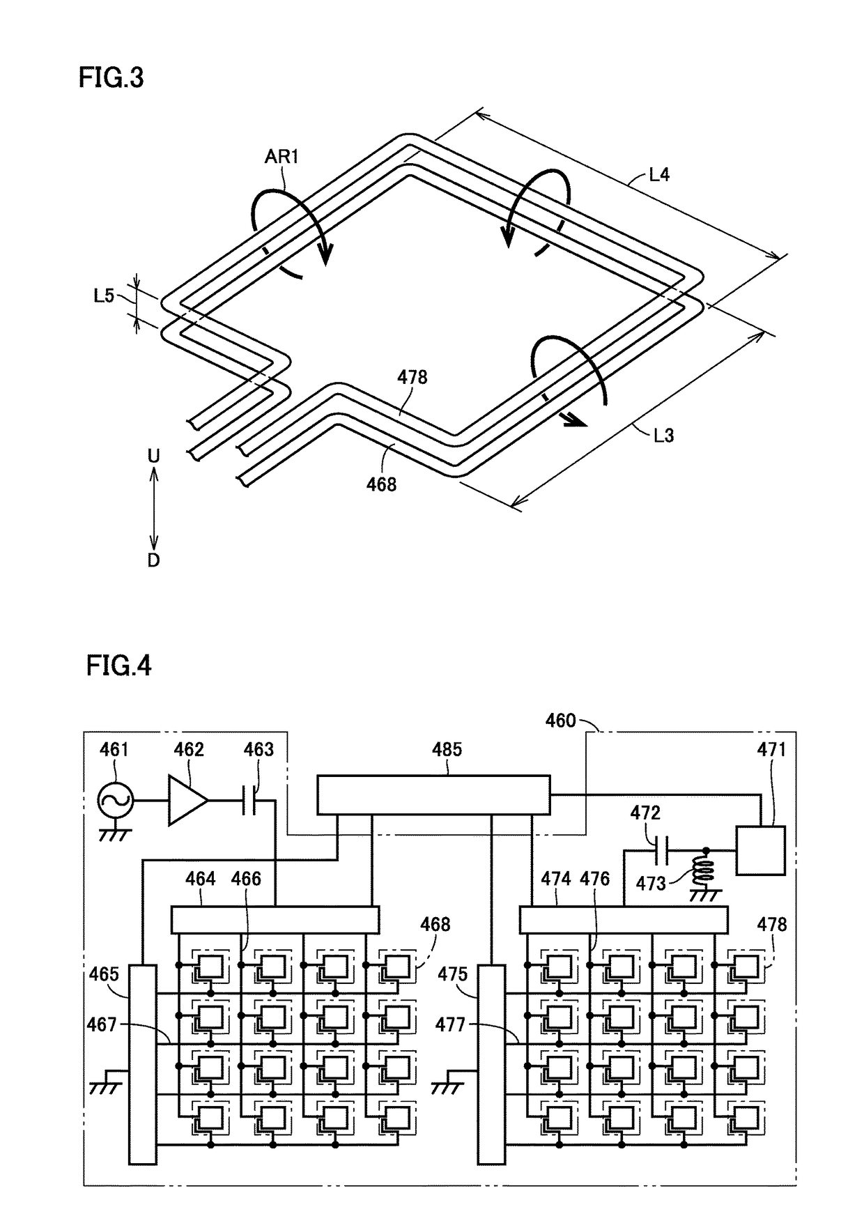
[0068]Although first coils 468 and second coils 478 have a rectangular shape in the first embodiment above (FIG. 3), first coils 468 and second coils 478 may have a triangular shape as shown in FIG. 5. Alternatively, as shown in FIG. 6, first coils 468 and second coils 478 may have another polygonal shape such as a hexagonal shape. According to the coils having a polygonal shape, the detection sensitivities can be rendered uniform by making the coils to have the same size and shape.

[0069]Alternatively, as shown in FIG. 7, first coils 468 and second coils 478 each including a coil portion having a circular outer shape may be employed. In FIG. 7, a plurality of pairs of coils formed of first coils 468 and second coils 478 are concentrically arranged.

Second Embodiment

[0070]In first coils 468 and second coils 478 shown in FIGS. 3, and 5 to 7, an induced voltage is generated under the influence of the magnetic field formed by power transmission coil 410, whic...

second embodiment

Variation of Second Embodiment

[0077]Although first coil 468A and second coil 478A each have the figure of eight by a pair of coil elements in the second embodiment above, the first coil and the second coil may each have a shape of petals by two pairs of coil elements as shown in FIG. 9. That is, a first coil 468D, which is an alternative to first coil 468A, is formed of a pair of coil elements 468E and 468F having the same number of turns and wound in opposite directions, and a pair of coil elements 468G and 468H having the same number of turns and wound in opposite directions. Coil elements 468E to 468H have a shape formed by arranging coil elements 468E to 468H on the same plane and successively connecting them in series. A second coil 478D, which is an alternative to second coil 478A, has the same configuration as first coil 468D.

[0078]Alternatively, as shown in a plan view of FIG. 10 and a cross-sectional view of FIG. 11, a pair of coils may be formed of a first coil 468I and a ...

third embodiment

[0079]Although the foreign object detector is provided in power transmission device 300 in each of the embodiments above, the foreign object detector may be provided in the vehicle (the power reception device).

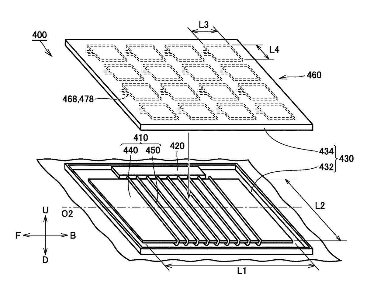
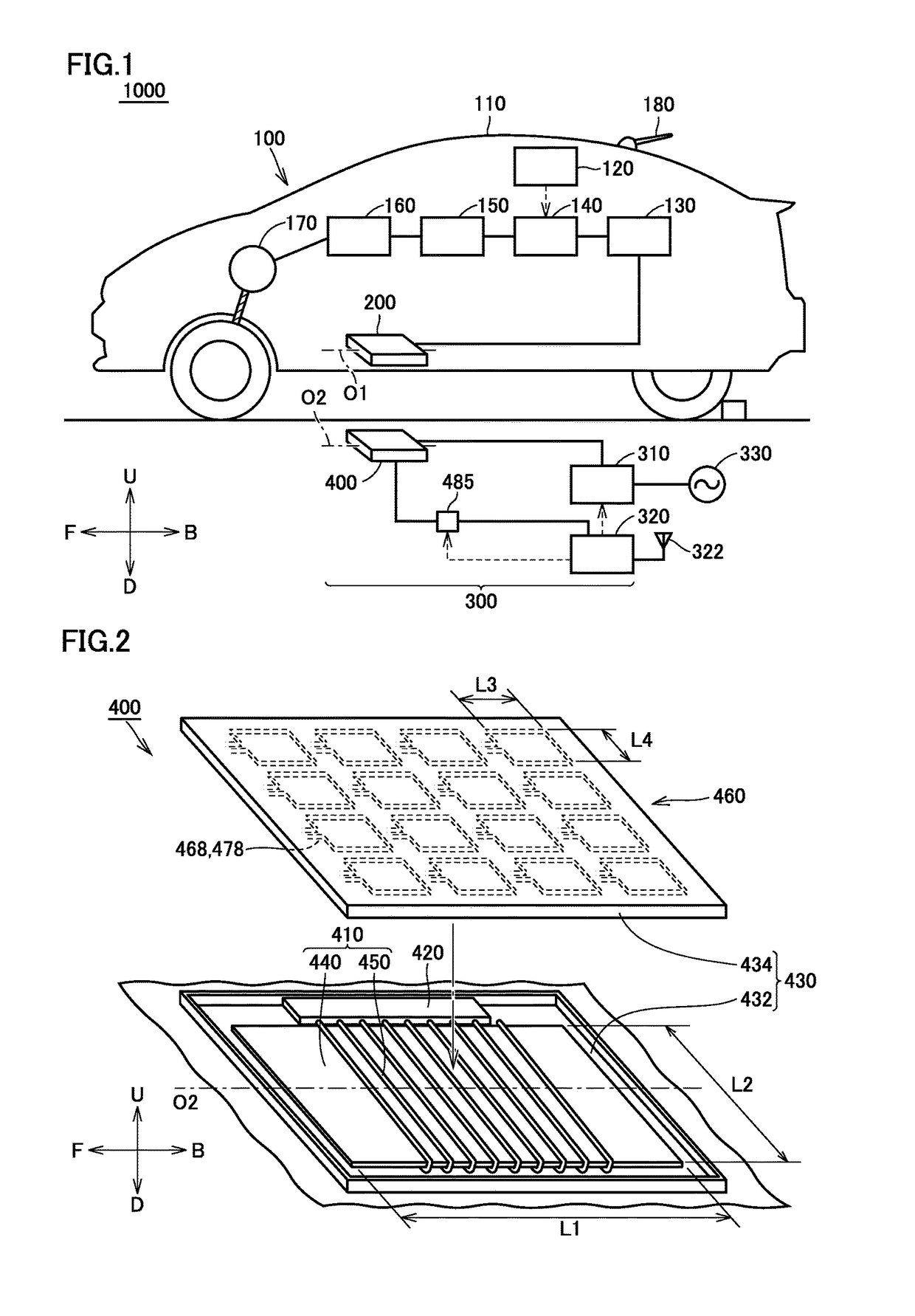
[0080]FIG. 12 is an exploded perspective view of a power reception unit 200A mounted on the vehicle in a third embodiment. Referring to FIG. 12, power reception unit 200A includes a power reception coil 210, a resonant capacitor 220, a housing 230, and a foreign object detector 260. Power reception coil 210 includes a core 240, and a conducting wire 250 wound around core 240. Housing 230 includes a shield 232 and a cover member 234.

[0081]Foreign object detector 260 includes a plurality of first coils 268 and a plurality of second coils 278. The plurality of first coils 268 and the plurality of second coils 278 are provided below power reception coil 210, and arranged on an inner surface of cover member 234 of housing 230 in the third embodiment. The plurality of second coils 2...


PUM

PropertyMeasurementUnit
lengths L1aaaaaaaaaa
distance L5aaaaaaaaaa
frequencyaaaaaaaaaa

Abstract

A foreign object detector includes a plurality of first coils and a plurality of second coils. The plurality of first coils are arranged along an upper surface of a power transmission coil. The plurality of second coils are provided to correspond to the plurality of first coils, with the second coils each being arranged to face a corresponding one of the first coils. An outer shape of each of the plurality of first coils and each of the plurality of second coils is smaller than an outer shape of the power transmission coil when the power transmission coil is viewed two-dimensionally from above the power transmission coil.

Description

[0001]This nonprovisional application is based on Japanese Patent Application No. 2014-138791 filed on Jul. 4, 2014 with the Japan Patent Office, the entire contents of which are hereby incorporated by reference.BACKGROUND OF THE INVENTION[0002]Field of the Invention[0003]The present invention relates to power transmission devices and power reception devices, and more particularly to detection of a foreign object between a power transmission device and a power reception device that exchange electric power in a contactless manner.[0004]Description of the Background Art[0005]There have been proposed a variety of contactless electric power transfer systems in which electric power is transferred from a power transmission device to a power reception device in a contactless manner.[0006]In such a contactless electric power transfer system, it is expected that a foreign object (an object that should not be present) will enter between the power transmission device and the power reception de...

Claims


Application Information

Patent Timeline
Patent Type & Authority Patents(United States)
IPC IPC(8): B60L11/18H02J50/60H01F38/14H02J50/12H02J50/40G01V3/10H02J50/70
CPCB60L11/182B60L11/1831G01V3/104H01F38/14H02J50/12H02J50/40H02J50/60H02J50/70B60L11/1829Y02T90/14Y02T10/7005Y02T10/7072Y02T90/12Y02T90/121Y02T90/122Y02T90/125B60L53/38B60L53/39B60L53/124B60L53/126B60L53/122Y02T10/70B60L53/12
Inventor NAKAMURA, TORUYAMADA, HIDEAKIKAWAIDE, MAKOTOHORIUCHI, SATORUSAITO, HIROAKI
Owner TOYOTA JIDOSHA KK
Why Eureka
Try Eureka