Measurement of evoked neural response

a neural response and neural response technology, applied in the field of neural response measurement, can solve the problems of conductive hearing loss, unable to derive suitable benefit from conventional hearing aid systems, and impede the normal mechanical pathway for sound to reach the hair cells in the cochlea

Inactive Publication Date: 2010-10-05
COCHLEAR LIMITED
View PDF71 Cites 2 Cited by
  • Summary
  • Abstract
  • Description
  • Claims
  • Application Information

AI Technical Summary

Benefits of technology

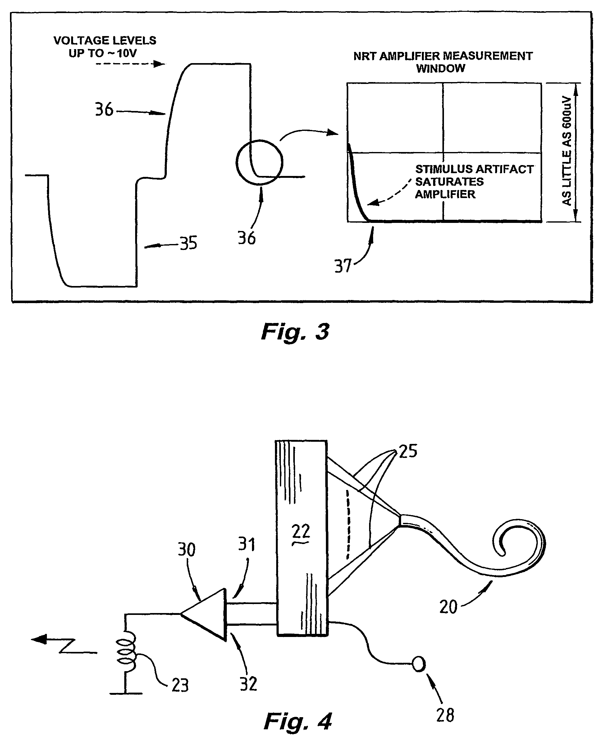
[0027]By resetting or altering the reference voltage of the amplifier during measurement, the present invention enables a high gain amplifier to be used in obtaining measurements of an evoked neural response, thus enabling detection of smaller neural response signals than prior art measurement methods. While resetting the reference voltage of the amplifier during measurement causes the output of the amplifier to represent the amplified sensed signal in piecewise fashion, the piecewise output signal segments can nevertheless be relatively easily reconstructed into a continuous waveform.
[0028]The step of altering the reference voltage of the high gain amplifier is preferably performed by setting the reference voltage to be equal to a present value of the sensed signal. This can be simply achieved by a sample-and-hold circuit having an input from the sensed signal. In such embodiments, a present dc-offset of the sensed signal is essentially removed, such that the high gain amplifier will only amplify and output variations of the sensed signal from the reference voltage. This enables such variations to be amplified by a relatively large amount, without the present dc-offset of the sensed signal and the slow variation of the signal causing the amplifier to enter saturation. It is to be appreciated that the present dc-offset is only “dc” when considered relative to the regularity with which the reference voltage of the high gain amplifier is altered.
[0029]Preferably, at the commencement of every sample period, the reference voltage of the high gain amplifier is altered to be equal to the present value of the sensed signal. In such embodiments of the invention, every sample obtained at the output of the high gain amplifier represents a change in the sensed signal which has occurred since the previous sample. With a sufficiently high sample rate, the change in the sensed signal during the duration of the sample period will be relatively small, enabling a larger gain to be applied to the signal without saturating the amplifier. Thus, even where a relatively large stimulus artefact contributes to the sensed signal and would otherwise cause saturation of the amplifier, the present invention enables high gain amplification of the sensed signal while avoiding saturation of the amplifier caused by large stimulus artefacts. That is, the method of the present invention assists in common mode rejection. In such embodiments of the present invention the obtained samples can simply be integrated or summed to obtain a continuous waveform representing the amplified sensed signal.
[0035]The device may comprise a cochlear implant. In such embodiments the sensor may comprise one or more electrodes of an electrode array of an implanted portion of the cochlear implant. The cochlear implant may be a totally implanted cochlear implant, as described in PCT / AU01 / 00769 by the present applicant, the contents of which are incorporated herein by reference. While the present invention is advantageous when used in typical cochlear implants having a relatively simple implanted portion and an external processor, embodiments of the present invention in which the device is a totally implanted cochlear implant may be of particular advantage, in that processing of the sensed signal is performed prior to transmission of the obtained samples over a transcutaneous RF link, thus reducing the impact of noise of the RF link on the accuracy of the sampled data.
[0036]The present invention may be particularly advantageous when used in conjunction with stimulus artefact cancellation schemes. For example, the present invention, when combined with the artefact cancellation technique disclosed in International Application No. PCT / AU02 / 00500 by the present applicant, the contents of which are incorporated herein by reference, may enable particularly accurate high resolution measurements of an evoked neural response to be obtained, despite the relatively small amplitude of the neural response and the presence of stimulus artefacts of significantly larger amplitude. For example, embodiments of the present invention may obtain samples of the amplified sensed signal from the output of the high gain amplifier, and as each sample is obtained, transmit that sample across a transcutaneous RF link such that processing of the samples can be performed externally. Alternatively, where the implanted portion has processing capability, internal processing may be performed and may avoid the effects of noise of the RF link on each sample.
[0044]means for setting a reference voltage at the reference input of the high gain amplifier equal to a present value of the sensed signal in order to prevent the high gain amplifier saturating with variations of the sensed signal.

Problems solved by technology

Of these types, conductive hearing loss occurs where the normal mechanical pathways for sound to reach the hair cells in the cochlea are impeded, for example, by damage to the ossicles.
These people are thus unable to derive suitable benefit from conventional hearing aid systems, no matter how loud the acoustic stimulus is made, because there is damage to or absence of the mechanism for nerve impulses to be generated from sound in the normal manner.
For implants with a large number of channels for stimulation, this process is quite time consuming and rather subjective as it relies heavily on the recipient's subjective impression of the stimulation rather than any specific measurement.
In such cases an incorrectly fitted implant may result in the recipient not receiving optimum benefit from the implant and in the cases of children may directly hamper the speech and hearing development of the child.
Whilst prior art systems of this type have proven useful in capturing and investigating evoked neural responses in the cochlea, there are still a number of intrinsic limitations associated with such systems, which have affected the quality of the measurements of the neural response.
In the main this has been due to the presence of stimulus artefacts in the measurement detected, resulting in a measurement being taken which is not necessarily a true indication of the actual ECAP response present.
The process of distinguishing the actual ECAP from stimulus artefacts has presented considerable difficulties, including problems such as the fact that the signals that are to be measured are extremely low level signals (down to the order of 10 uV).
Providing for a system that is firstly able to deliver a stimulus of sufficient amplitude and also to detect the elicited response of the nerves to that particular stimulation has therefore been problematic.
In order to properly resolve the very small neural signal a large amplifier gain is required (typically of about 60 dB to 70 dB), however the neural signal is often superimposed on a much larger artefact which makes it difficult to extract the neural signal of interest due to the finite dynamic range of the amplifier and the need for high gain to resolve the signal.
Such a system does not provide immediate results which can be acted upon, as the measured results often require time consuming analysis before they can be used.
With the need to use such results immediately to adjust patient T and C levels, existing methods are not satisfactory.

Method used


Image

  • Measurement of evoked neural response
  • Measurement of evoked neural response
  • Measurement of evoked neural response

Examples


Embodiment Construction

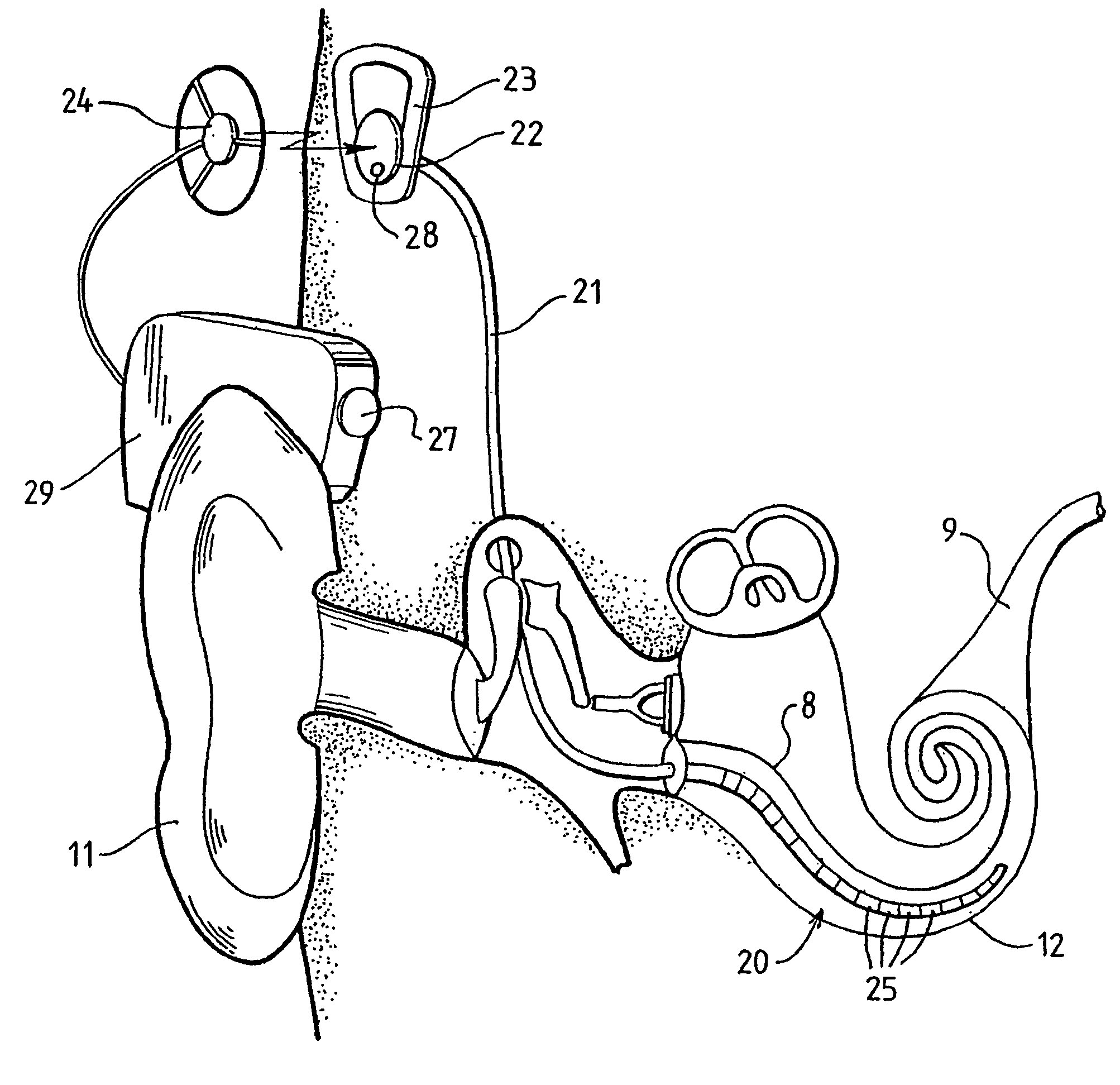
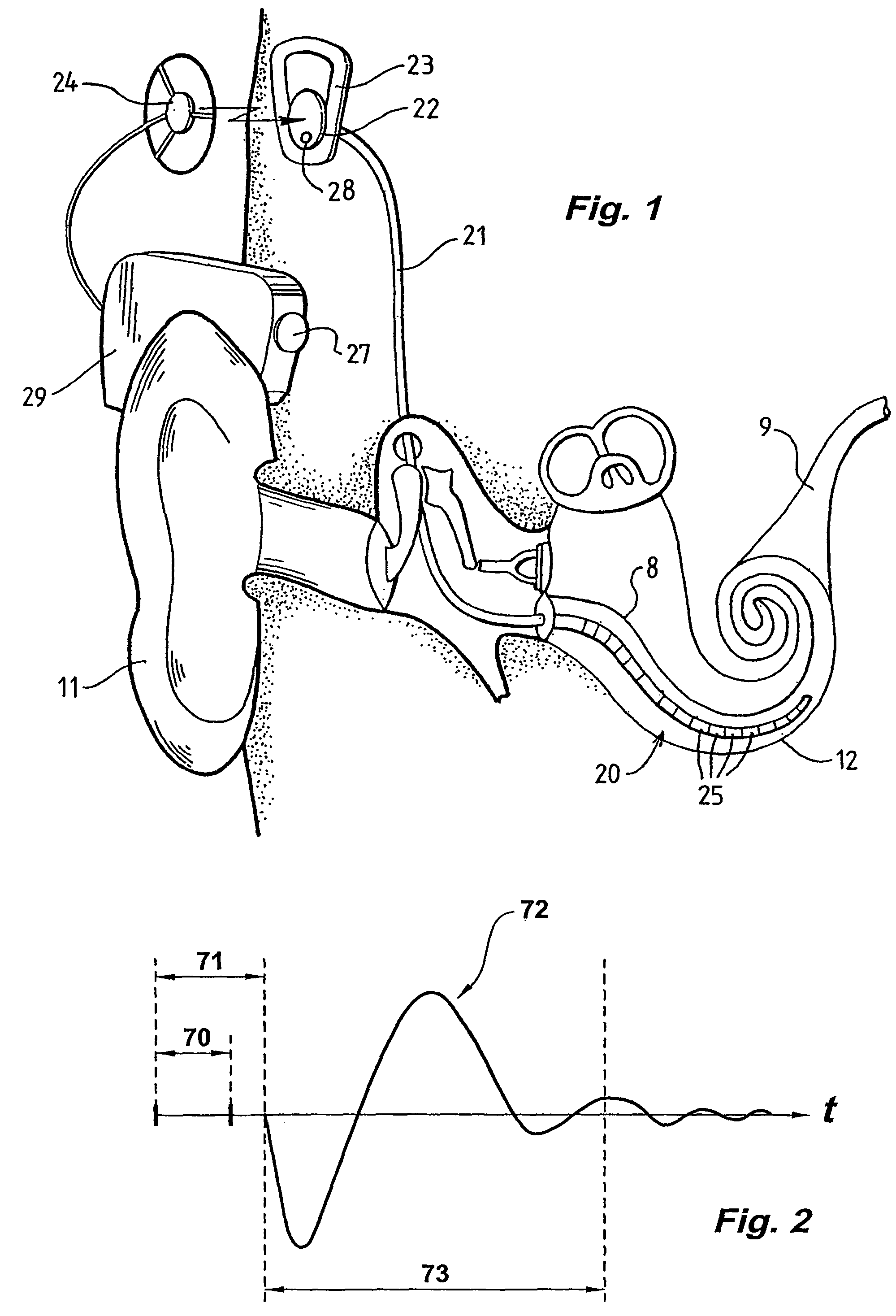
[0052]While the present invention is not directed solely to a cochlear implant, it is appropriate to briefly describe the construction of one type of known cochlear implant system with reference to FIG. 1.

[0053]Known cochlear implants typically consist of two main components, an external component including a speech processor 29, and an internal component including an implanted receiver and stimulator unit 22. The external component includes a microphone 27. The speech processor 29 is, in this illustration, constructed and arranged so that it can fit behind the outer ear 11. Alternative versions may be worn elsewhere on the recipient's body. Attached to the speech processor 29 is a transmitter coil 24 that transmits electrical signals to the implanted unit 22 via a radio frequency (RF) link.

[0054]The implanted component includes a receiver coil 23 for receiving power and data from the transmitter coil 24. A cable 21 extends from the implanted receiver and stimulator unit 22 to the c...


PUM


Abstract

A method and device for measuring an evoked neural response comprising a sensor (25) for obtaining a sensed signal representing the evoked neural response, a high gain amplifier (30) having a signal input (31) for receiving the sensed signal and having a reference input (32), and means for altering or setting a reference voltage at the reference input (32) to prevent the amplifier (30) saturating with variations of the sensed signal.

Description

CROSS-REFERENCE TO RELATED APPLICATIONS[0001]This application claims the priority of and is a national stage application of PCT Application No. PCT / AU2003 / 00001151, entitled, “Method and Apparatus for Measurement Of Evoked Neural Response,” filed on Sep. 4, 2003, which claims the priority of Australian Patent No. 2002951218, filed on Sep. 4, 2002. The entire disclosure and contents of the above applications are hereby incorporated by reference.FIELD OF THE INVENTION[0002]The present invention relates to measurement of a neural response evoked by a stimulus, and in particular to a method and device for measuring the evoked neural response in the presence of stimulus artefacts.BACKGROUND OF THE INVENTION[0003]Hearing loss, which may be due to many different causes, is generally of two types, conductive and sensorineural. Of these types, conductive hearing loss occurs where the normal mechanical pathways for sound to reach the hair cells in the cochlea are impeded, for example, by dama...

Claims


Application Information

Patent Timeline
Patent Type & Authority Patents(United States)
IPC IPC(8): A61N1/00A61B5/04A61B5/0484A61N1/36H04R25/00
CPCA61B5/04001A61B5/0484A61N1/36032H04R25/606A61B5/7217A61N1/36039A61B5/24A61B5/377
Inventor EDER, HELMUT CHRISTIANHURLEY, PADRAIG JOSEPHMONEY, DAVID KERRYNYGARD, TONY MIKEAL
Owner COCHLEAR LIMITED
Why Eureka
Try Eureka