Battery management systems for energy storage devices

a technology of energy storage device and management system, which is applied in the field of battery management system for energy storage device, can solve the problems of limited capacity of rechargeable batteries, inability to maintain a given energy density, and inability to use long-term, and achieve the effect of reliable impedance metri

Inactive Publication Date: 2016-11-17
AMBRI
View PDF10 Cites 116 Cited by
  • Summary
  • Abstract
  • Description
  • Claims
  • Application Information

AI Technical Summary

Benefits of technology

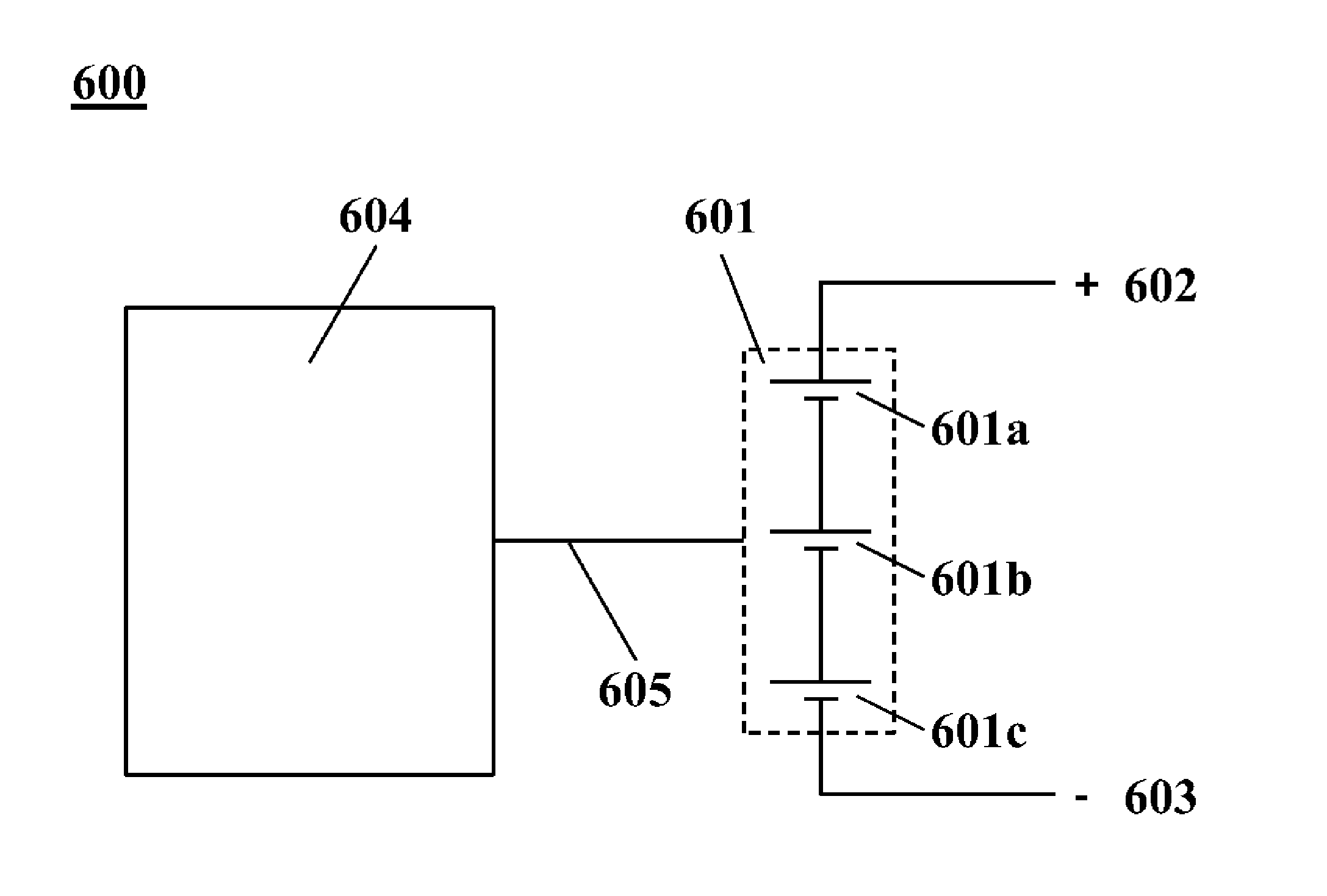
[0010]For serial operation, the battery management system can include voltage sensing of cells and ballasting provisions that are connected to the battery management system through ballasting lines. In some examples, the ballasting lines are electrical wires. The impedance of the ballasting lines, however, can impact the amount of voltage drop across the lines. The impedance of these lines can vary with temperature and in accordance with the material used in the lines. Because the impedance of the ballasting lines can vary with temperature, and because the temperature of an electrochemical system (e.g., a liquid metal battery) can vary during use, the impedance of the ballasting lines can vary during operation of the liquid metal battery. In some situations, algorithms of the battery management system that regulate the operation of the liquid metal battery using an assumed impedance of the ballasting lines (e.g., an impedance at room temperature) may arrive at erroneous results at higher operating temperatures. A battery management system can include hardware and software to dynamically compensate for variations in impedance. The software can be fixed in a non-volatile storage medium, such as a memory location. This can advantageously enable algorithms of the battery management system that regulate cell balancing to have a reliable metric of impedance on the sensing lines, and to thereby control balancing current appropriately.

Problems solved by technology

While batteries are presently available, recognized herein are various limitations associated with such batteries.
For example, rechargeable batteries may not be able to retain a given energy density after a certain number of charge / discharge cycles, making the long term use of these devices practically infeasible.
While some batteries may have longer operating lifetimes than others, such batteries may not have an energy density that is suited for commercial use.
The failure condition can be a breach.

Method used


Image

  • Battery management systems for energy storage devices
  • Battery management systems for energy storage devices
  • Battery management systems for energy storage devices

Examples


Embodiment Construction

[0043]While various embodiments of the invention have been shown and described herein, it will be obvious to those skilled in the art that such embodiments are provided by way of example only. Numerous variations, changes, and substitutions may occur to those skilled in the art without departing from the invention. It should be understood that various alternatives to the embodiments of the invention described herein may be employed. It shall be understood that different aspects of the invention can be appreciated individually, collectively, or in combination with each other.

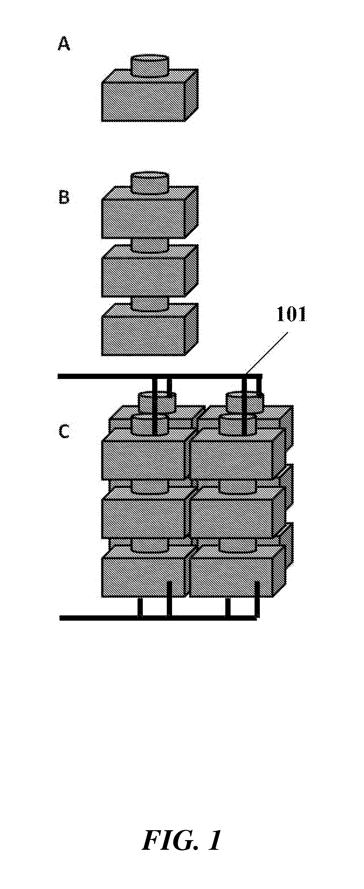
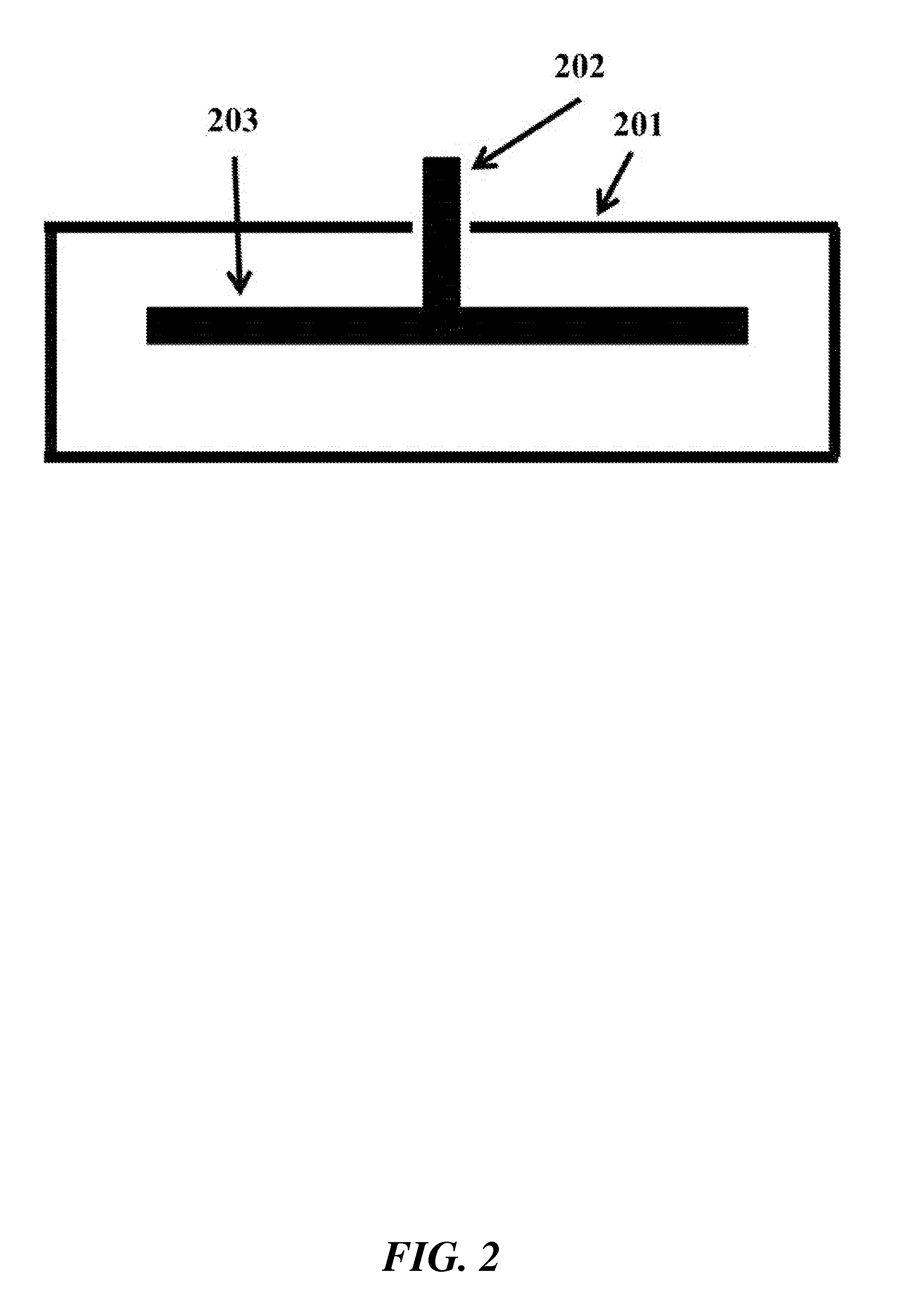
[0044]The term “cell,” as used herein, generally refers to an electrochemical cell. A cell can include a negative electrode of material ‘A’ and a positive electrode of material ‘B’, denoted as A∥B. The positive and negative electrodes can be separated by an electrolyte. A cell can also include a housing, one or more current collectors, and a high temperature electrically isolating seal. In some cases, a cell can ...


PUM

PropertyMeasurementUnit
operating temperatureaaaaaaaaaa

Abstract

Disclosed herein are methods and systems for monitoring and / or regulating energy storage devices. Examples of such monitoring and / or regulating include cell balancing, dynamic impedance control, breach detection and determination of state of charge of energy storage devices.

Description

CROSS-REFERENCE[0001]This application claims the benefit of U.S. Provisional Application No. 61 / 892,326, filed Oct. 17, 2013, which is entirely incorporated herein by reference.BACKGROUND[0002]A battery is a device capable of converting chemical energy into electrical energy. Batteries are used in many household and industrial applications. In some instances, batteries are rechargeable such that electrical energy, which may be converted from non-electrical energy (e.g., mechanical energy), is capable of being stored in the battery as chemical energy.[0003]There are generally two types of batteries: disposable batteries (primary batteries), which are designed to be used once and discarded, and rechargeable batteries (secondary batteries), which are designed to be recharged and used multiple times. There are various shapes and sizes of batteries, such as, for example, miniature cells used to power small electronic devices, and large batteries, which may be used to provide power for co...

Claims


Application Information

Patent Timeline
Patent Type & Authority Applications(United States)
IPC IPC(8): H01M10/42H01M10/39H02J9/06H01M4/44H01M4/38H02J7/00H01M10/48H01M4/42
CPCH01M10/425H01M10/486H01M10/399H01M4/42H01M4/44H01M4/387H01M2010/4271H02J7/0068H02J9/061H01M2220/10H01M2220/20H01M2220/30H01M2010/4278H01M4/38H01M4/381H01M4/382H01M10/39H01M10/42H02J7/0014H02J7/0048Y02E60/10H02J7/007194
Inventor NAYAR, HARILEKATSAS, NICHOLASBRADWELL, DAVID J.MCNELEY, MICHAEL J.MODEST, ZACHARY T.
Owner AMBRI
Why Eureka
Try Eureka