Monitoring device for secondary battery, battery pack, and protection system for secondary battery

Active Publication Date: 2016-11-17
GS YUASA INT LTD
View PDF3 Cites 5 Cited by
  • Summary
  • Abstract
  • Description
  • Claims
  • Application Information

AI Technical Summary

Benefits of technology

[0006]An object of the present invention is to obtain safety performance suitable

Problems solved by technology

Uniformly applying the safety performance during running may result i

Method used


Image

  • Monitoring device for secondary battery, battery pack, and protection system for secondary battery
  • Monitoring device for secondary battery, battery pack, and protection system for secondary battery
  • Monitoring device for secondary battery, battery pack, and protection system for secondary battery

Examples


first embodiment

[0031]A first embodiment will be described with reference to FIGS. 1 to 5.

1. Configuration of Battery Pack 20

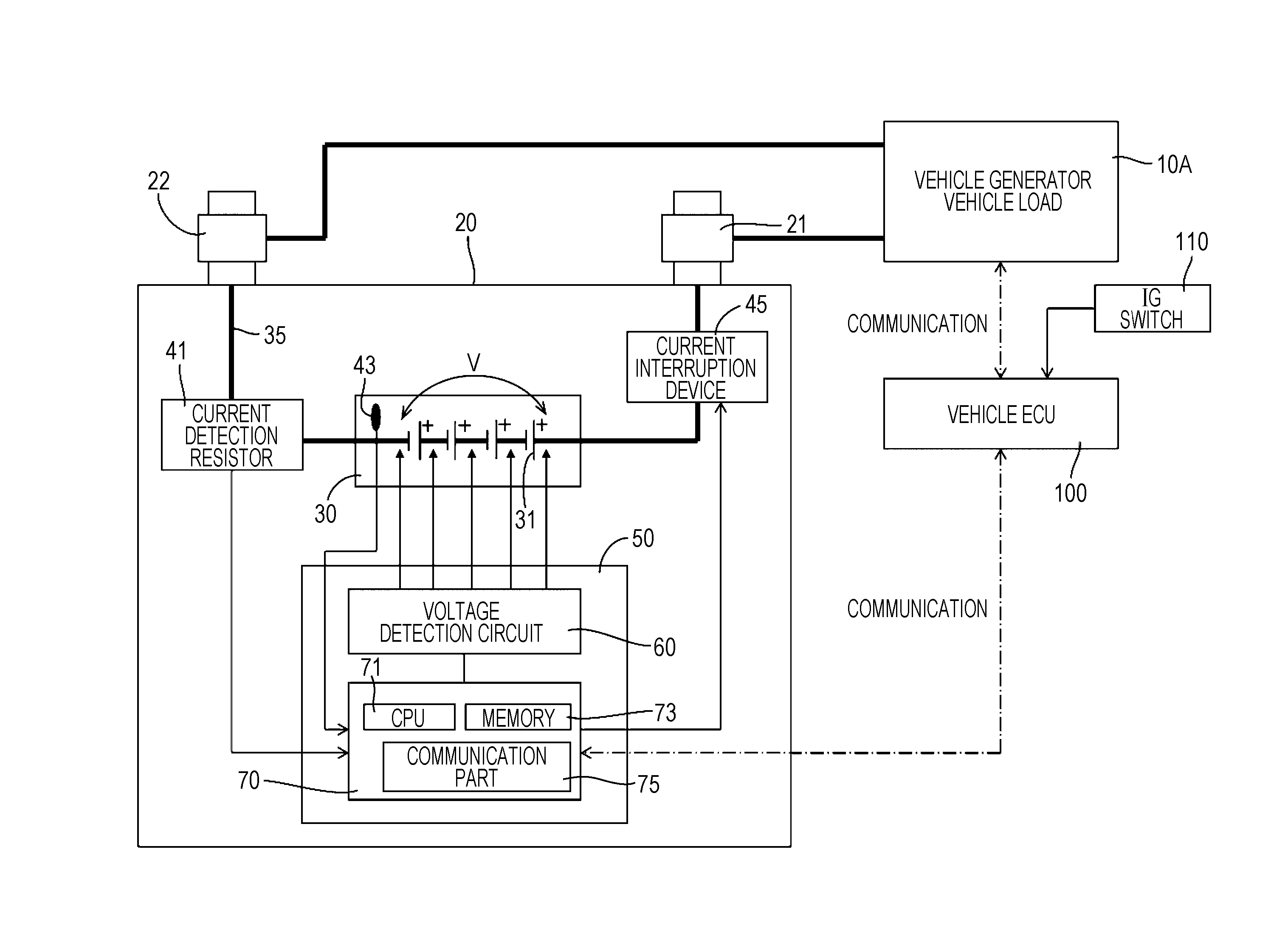
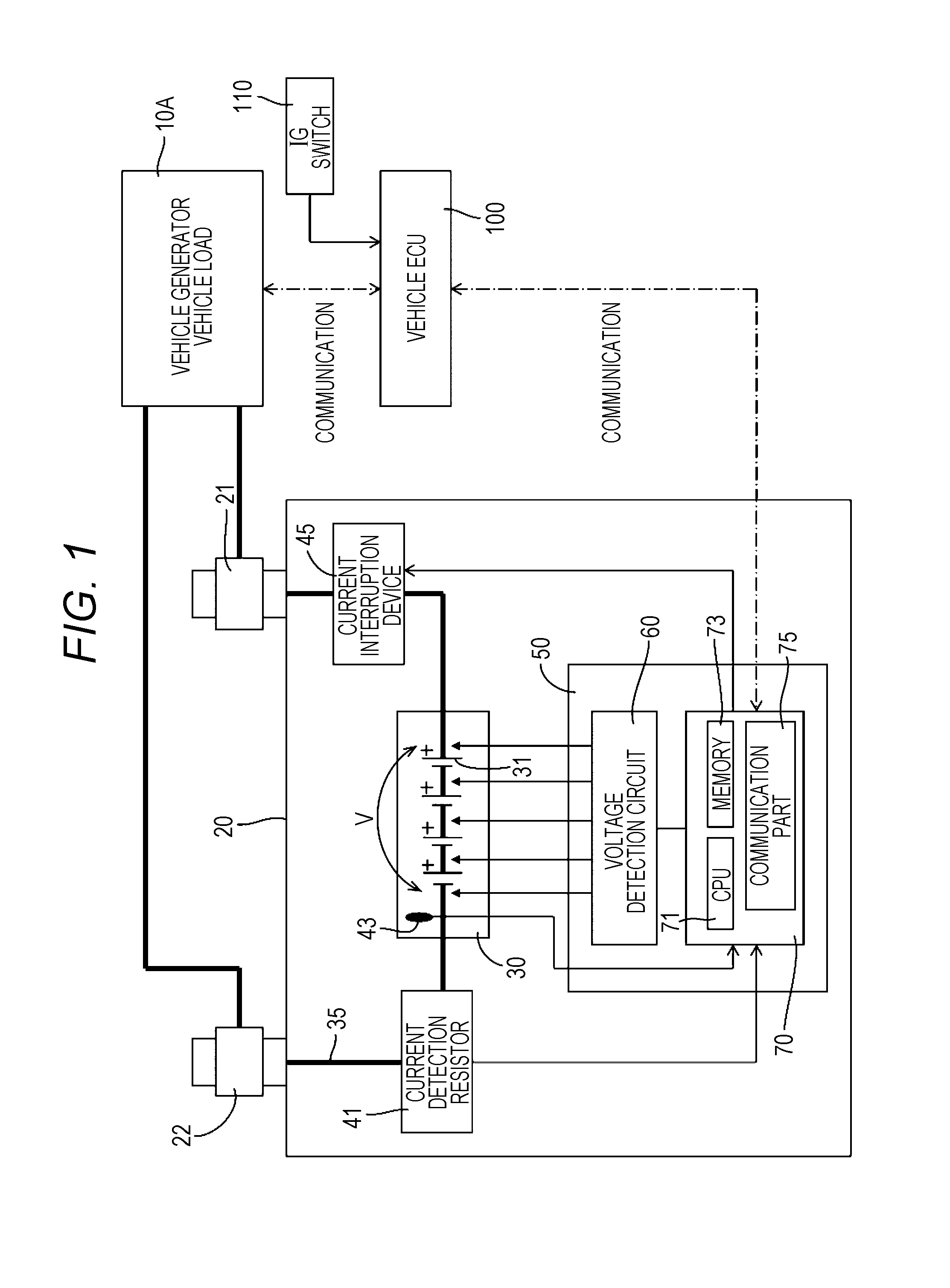
[0032]FIG. 1 is a diagram illustrating a configuration of a battery pack 20 in the present embodiment. The battery pack 20 of the present embodiment is, for example, mounted on an electric vehicle or a hybrid electric vehicle to supply electric power to a vehicle load 10A such as an engine starting device, and to receive charge from a vehicle generator (an alternator) 10A. Reference numeral 21 shown in FIG. 1 denotes a positive electrode terminal of the battery pack 20, and reference numeral 22 denotes a negative electrode terminal.

[0033]As shown in FIG. 1, the battery pack 20 has an assembled battery 30, a current detection resistor 41, a thermistor 43, a current interruption device 45, and a battery manager (hereinafter, referred to as BM) 50 that manages the assembled battery 30. In this embodiment, the assembled battery 30 is made up of a plurality of lithium ion secondar...

second embodiment

[0063]Next, a second embodiment of the present invention will be described with reference to FIGS. 6 to 9.

[0064]A battery pack 20 of the second embodiment has an assembled battery 30, a current detection resistor 41, a current interruption device 45, and a BM 50 that manages the assembled battery 30 as with the battery pack 20 in the first embodiment. In the first embodiment, the example has been described in which in the control part 70 of the BM 50, it is detected whether or not the use state of the assembled battery 30 is the first use state, and in accordance with the detection result, the protection condition is switched. In the second embodiment, in the control part 70 of the BM 50, it is detected which of a first use state to a third use state the use state of the assembled battery 30 corresponds to, and in accordance with a detection result, protection conditions A to C are switched.

[0065]The “first use state” is a state where the battery pack 20 is used in a vehicle during ...

third embodiment

[0076]Next, a third embodiment of the present invention will be described with reference to FIG. 10.

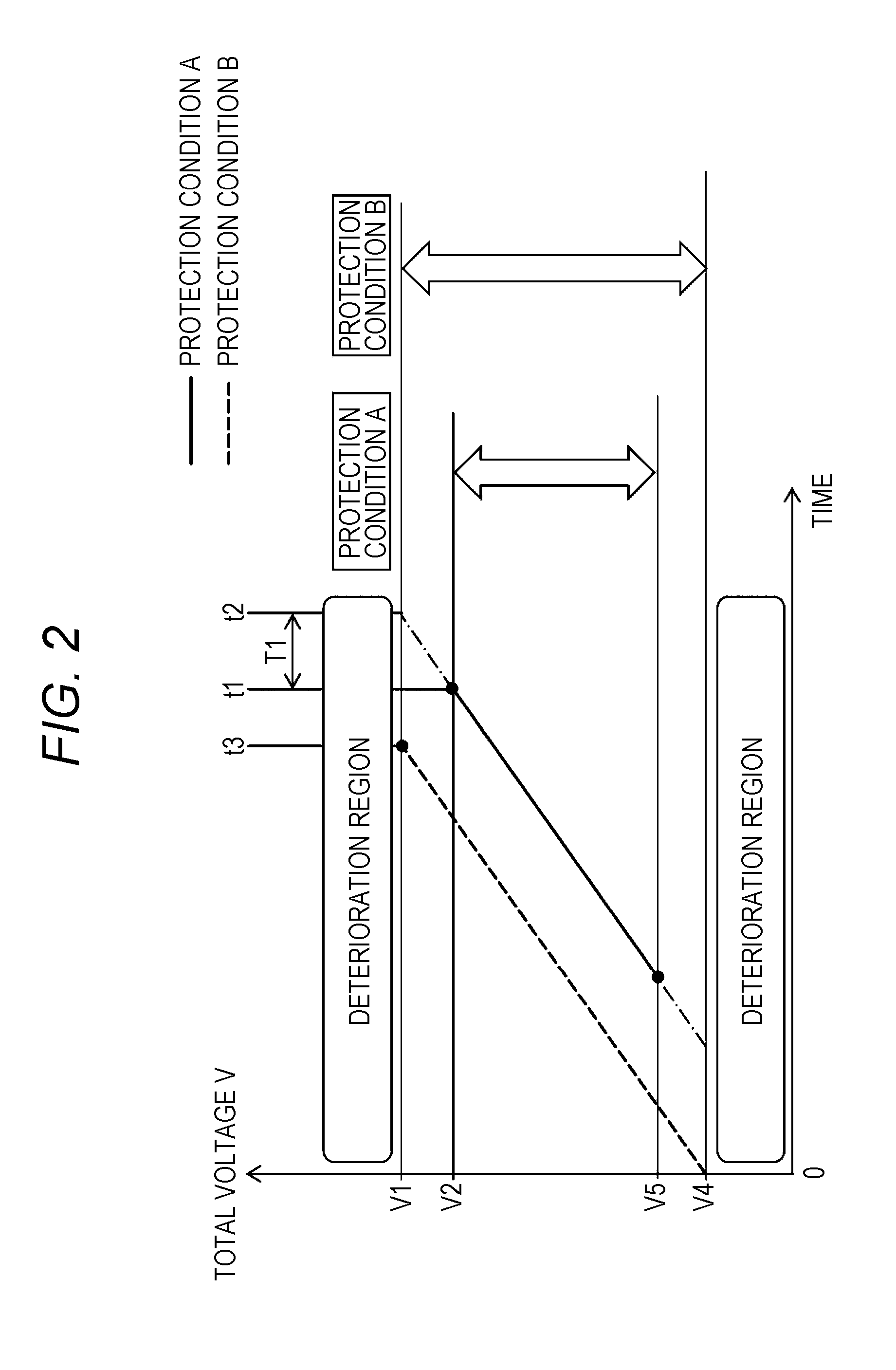
[0077]In the first embodiment, as the example of switching between the protection conditions A and B, the example of switching the use range of the assembled battery 30 has been described. That is, the example has been described in which in the control part 70 of the BM 50, it is detected whether or not the use state of the assembled battery 30 is the first use state, and in accordance with the detection result, the use range of the total voltage V of the assembled battery 30 is switched. Moreover, the configuration is employed in which the prescribed period T from the establishment of the condition for interrupting the assembled battery 30 to the interruption of the assembled battery 30 is also switched. With the configuration, in the case where the protection condition A is applied (in the case of the first use state), the command is given to the current interruption device 45 to in...


PUM


Abstract

A monitoring device for a secondary battery includes: a detection part that detects a use state of the secondary battery; and a switching part, wherein the switching part switches a protection condition applied to the secondary battery in accordance with the user state of the secondary battery.

Description

CROSS-REFERENCE TO RELATED APPLICATIONS[0001]This application claims the benefit of Japanese patent applications No. 2015-120216, filed on Jun. 15, 2015, and No. 2016-115771, filed on Jun. 9, 2016, which are incorporated by reference.FIELD[0002]The present invention relates to a technique regarding a protection condition applied to a secondary battery.BACKGROUND[0003]For example, a 12 V battery mounted on an automobile is used for electric power supply to an engine starting device and various vehicle loads, and is charged from an alternator. In order to use such a battery safely and efficiently, there is a battery in which a battery monitoring device and a current interruption device is mounted (JP 2013-195183 A).[0004]In general, safety performance required by a secondary battery is different between during running and during parking, for example, and higher safety is required during running. Uniformly applying the safety performance during running may result in excessive quality o...

Claims


Application Information

Patent Timeline
IPC IPC(8): H01M10/48H01M10/0525B60L3/04H01M10/42B60K1/04H01M2/10H01M2/34H01M50/202H01M50/249H01M50/574
CPCH01M10/48H01M2/1077H01M10/0525H01M2/34H01M2010/4271B60K1/04B60L3/04H01M2220/20H01M10/425G01R31/382B60L58/10G01R31/36H01M10/42H01M10/4207H01M10/4285H02J7/00H02J7/00306H02J7/0029H02J7/00302H01M50/202H01M50/574H01M50/249B60L2240/547B60L58/14B60L58/13B60L58/15H02J7/00304Y02E60/10Y02T10/70H02J7/16H02J7/0031H02J7/0032
Inventor KAWAUCHI, TOMOHIRONAKAMURA, MASASHI
Owner GS YUASA INT LTD
Why Eureka
Try Eureka