
Swivel Assembly for a Vacuum Accessory

Active Publication Date: 2016-11-24
EMERSON ELECTRIC CO
View PDF4 Cites 0 Cited by
  • Summary
  • Abstract
  • Description
  • Claims
  • Application Information

AI Technical Summary

Benefits of technology

The patent describes swivel systems and swivel assemblies for connecting a vacuum appliance to a vacuum accessory. These assemblies allow the vacuum appliance to pivot relative to the accessory about two independent axes. The swivel systems include a vacuum adapter and a connector that allows the adapter to pivot about the accessory, as well as a plenum chamber that is connected to the vacuum hoses to balance airflow. These swivel systems and assemblies improve the versatility and efficiency of vacuum appliances and other tools by enabling them to rotate in multiple directions and providing balanced airflow configurations.

Problems solved by technology

As a result, the swivel hose coupling is overly complex and difficult to assemble, and uses a threaded connection, which may become unscrewed, to engage the hose and the coupling.
While the arrangement shown in the '429 Patent does indeed permit the desired rotational movement, it is not without limitations.
This type of arrangement also includes many parts to achieve the coupling, and, thus, would be not only complicated to use, but also expensive to produce and maintain.

Method used


Image

  • Swivel Assembly for a Vacuum Accessory
  • Swivel Assembly for a Vacuum Accessory
  • Swivel Assembly for a Vacuum Accessory

Examples


first embodiment

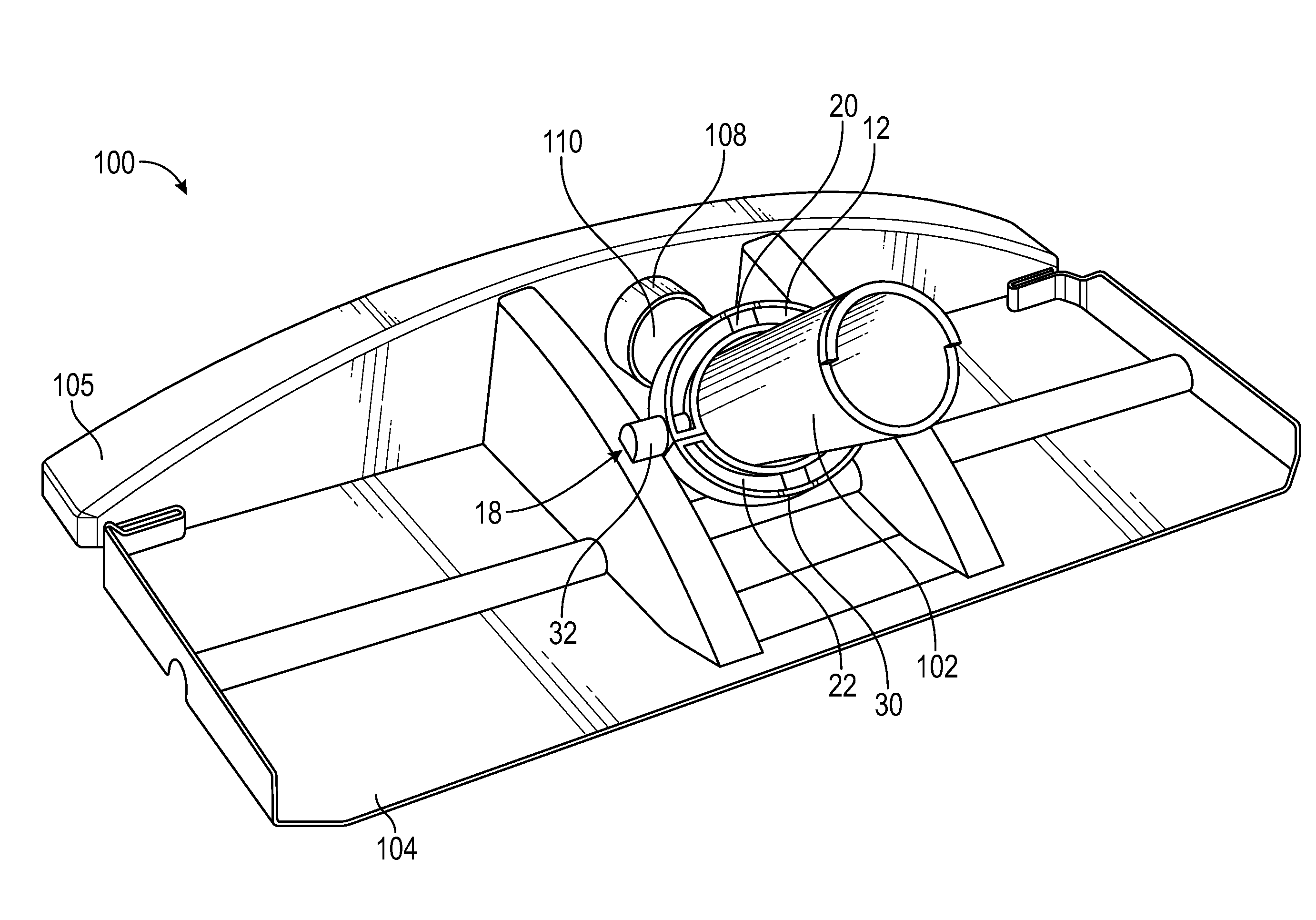
[0058]FIG. 3A illustrates a swivel system including an exemplary assembled swivel link assembly in accordance with aspects of the present disclosure. FIG. 3B illustrates a side view of the assembly of FIG. 2 in accordance with aspects of the present disclosure. FIG. 4A illustrates a first perspective view of the swivel link assembly of FIG. 2 in use with a vacuum accessory. FIG. 4B illustrates a second perspective view of the swivel link assembly of FIG. 2 in use with a vacuum accessory. These figures will be described in conjunction with one another.

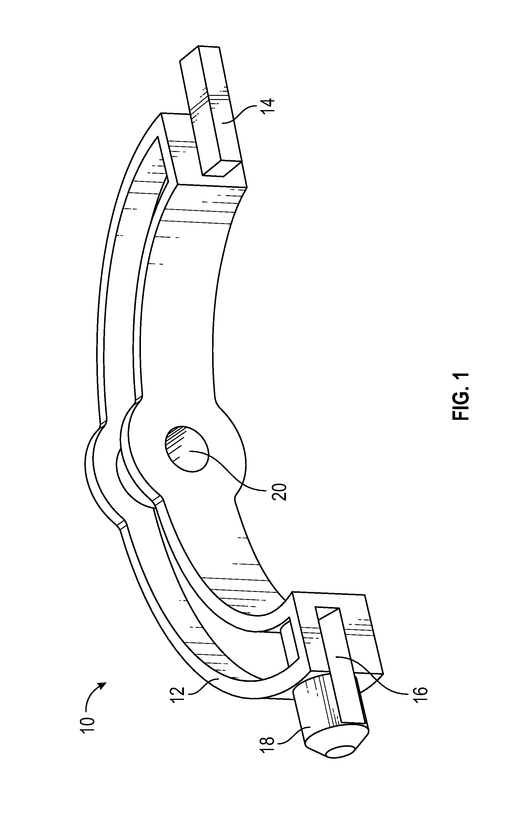
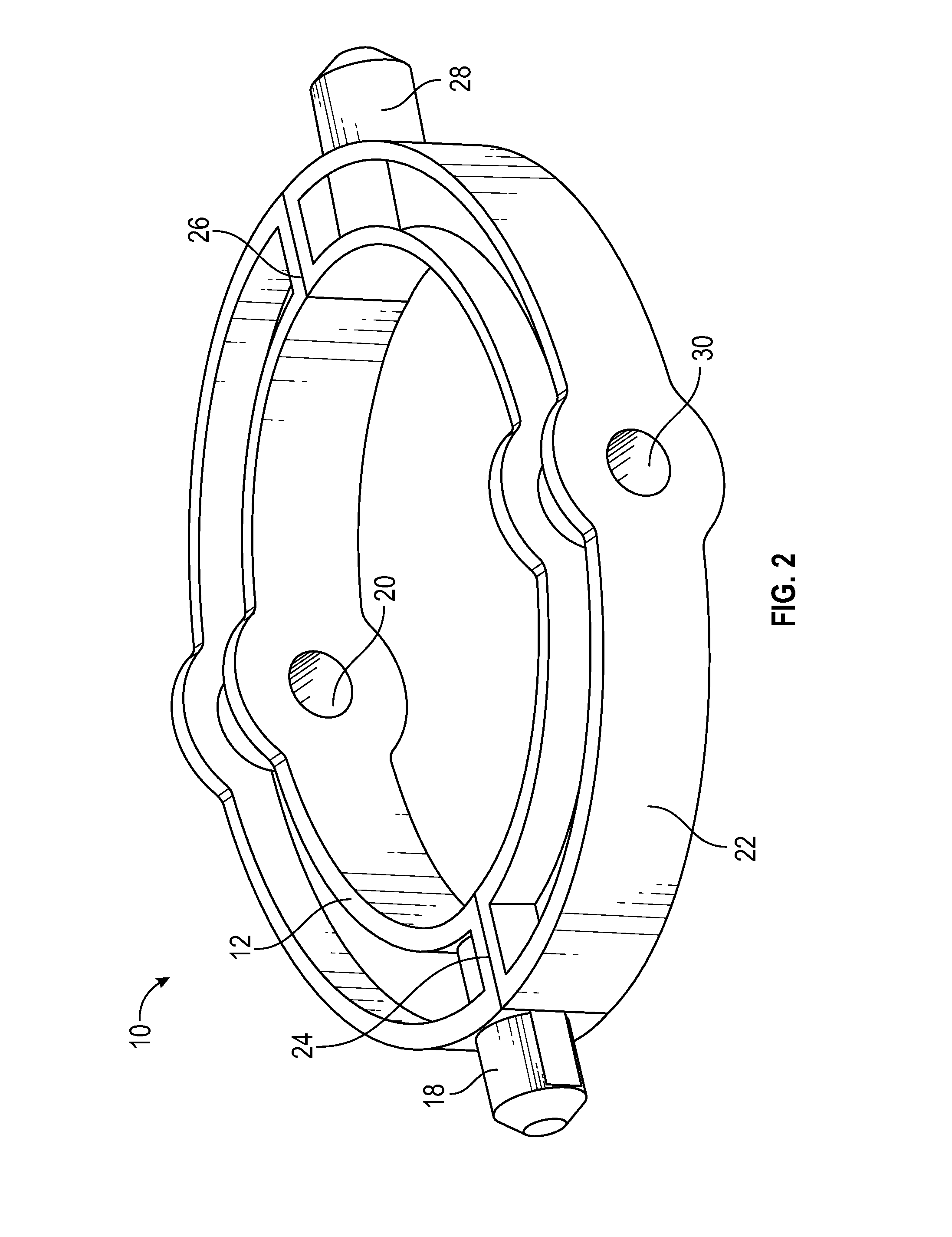
[0059]First vacuum pivot system 100 can include assembly 10 (as described, for example, in FIGS. 1 and 2, above), vacuum adapter 102, accessory 104, vacuum head 105. System 100 can additionally include air inlet 108 and conduit 110 that can be adapted to be disposed between vacuum adapter 102 and air inlet 108.

[0060]Assembly 10 can be coupled with accessory 104 by coupling first swivel joint 18 to swivel joint connector 32. Additionally...

second embodiment

[0076]FIG. 7 illustrates a partial cut-away front view of the swivel system illustrated in FIG. 6A. FIG. 8 illustrates a top view of a swivel system illustrated in FIG. 6A with particular focus on the relative spacing of the air outlets in accordance with certain aspects of the present disclosure.

[0077]Referring specifically to FIG. 7, the airflow balancing discussed in greater detail above can be accomplished by designing accessory 204 within certain parameters. For example, by adjusting the width 204W of accessory 204 and setting angles Θ1 and Θ2 appropriately, airflow can be optimized. For example, in an exemplary and non-limiting illustrative embodiment, 204W can be set to eighteen inches, Θ1 set to nineteen degrees, and Θ2 set to fifteen degrees. With this width 204W, Θ1 and Θ2 can be varied up to + / −eight degrees without a significant loss in airflow optimization. Additionally, other widths 204W and angles Θ1 and Θ2 are contemplated as well, is including those with similar pro...


PUM


Abstract

Described are swivel systems and swivel assemblies for connecting a vacuum appliance to a vacuum accessory. The assembly can be adapted to be coupled to the accessory to permit the appliance to pivot relative to the accessory offset from a center of the accessory. The swivel system can include a vacuum adapter and a connector adapted to permit the vacuum adapter to pivot about a vacuum accessory. A plenum chamber can be formed in the adapter that is in fluid communication with one or more vacuum hoses to balance the airflow within the adapter.

Description

CROSS REFERENCE TO RELATED APPLICATIONS[0001]This application is a non-provisional application of, and claims priority to, U.S. Application Ser. No. 62 / 156,521, entitled “Swivel Assembly for Connecting a Wand to a Vacuum Accessory and Associated Accessory Tool for Use on Hard Surfaces”, filed May 4, 2015. This application is also a continuation-in-part application of, and claims priority to, U.S. application Ser. No. 14 / 833,326, entitled “Swivel Assembly for Connecting a Wand to a Vacuum Accessory and Associated Accessory Tool for Use on Hard Surfaces”, filed Aug. 24, 2015, which is a divisional of, U.S. application Ser. No. 14 / 509,411, filed Oct. 8, 2014, now U.S. Pat. No. 9,241,603. Each of the above referenced applications are incorporated herein by specific reference.STATEMENT REGARDING FEDERALLY SPONSORED RESEARCH OR DEVELOPMENT[0002]Not applicable.REFERENCE TO APPENDIX[0003]Not applicable.BACKGROUND OF THE INVENTION[0004]Field of the Invention[0005]The inventions disclosed and...

Claims


Application Information

Patent Timeline
IPC IPC(8): A47L9/24A47L9/02
CPCA47L9/02A47L9/242
Inventor LUTZ, CHRISTOPHERWILLIAMS, MATTSWINDALL, JAIME
Owner EMERSON ELECTRIC CO
Learn More