

Vacuum brake booster
a technology of vacuum brake booster and rotor, which is applied in the direction of braking system, vehicle components, air treatment devices, etc., can solve the problems of noisy operation of conventional vacuum brake booster, and achieve the effect of simple assembly
- Summary
- Abstract
- Description
- Claims
- Application Information
AI Technical Summary
Benefits of technology
Problems solved by technology
Method used
Image

Examples
Embodiment Construction
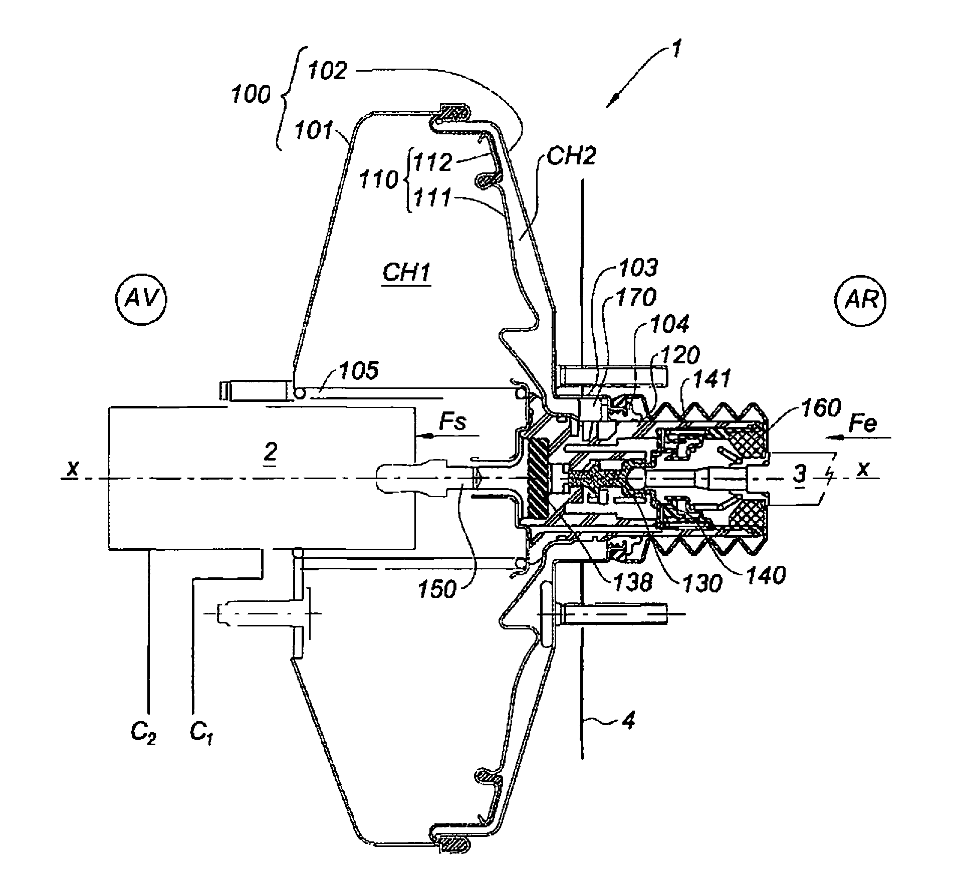
[0014]As shown by FIG. 1, the vacuum brake booster is associated with master cylinder 2, that is, a tandem master cylinder shown schematically, which supplies pressurized brake fluid to the vehicle's brake line(s) C1, C2. It is attached to firewall 4 separating the passenger compartment from the engine compartment.
[0015]By convention, master cylinder 2 is located in front (AV) of brake booster 1 and control rod 3 is in the rear (AR).
[0016]Vacuum brake booster 1 is actuated by control rod 3, connected to the brake pedal. Brake booster 1 consists of vacuum housing 100, with two chambers CH1, CH2. Chamber CH1 is a vacuum chamber (P12 is a vacuum / pressure chamber, separated from chamber CH1 by piston 110. Chamber CH1 is referred to as a vacuum chamber and chamber CH2 as a variable pressure chamber. The admission of air at atmospheric pressure, Patm, is controlled by the brake pedal, which acts through control rod 3 upon an air intake valve described below. Piston 110 is connected to mas...
PUM
 Abstract
Description
Claims
Application Information