System and Method for Determination of Distance Between Two Points in 3-Dimensional Space

a technology of distance measurement and distance measurement, applied in the field of distance measurement, can solve the problems of physical impossible, inconvenient, or time-consuming, and the inability to determine the length of the system other than the height, and achieve the effect of convenient and accurate measurement, no set-up, and high transportability

Inactive Publication Date: 2016-11-24
AN TAE HWI +1
View PDF4 Cites 2 Cited by
  • Summary
  • Abstract
  • Description
  • Claims
  • Application Information

AI Technical Summary

Benefits of technology

[0009]Contrary to the prior art systems above, in at least one embodiment, the present system and method provide the capability of finding the distance between two points residing on a surface or surfaces in space with ease and accuracy, where the user is not required to change position. Furthermore, in at least one embodiment, the present system and method provide the capability of finding the distance between two points in space with ease and accuracy, regardless of the orientation of the length in question. Additionally, in at least one embodiment, the present system and method allows the finding of the distance between two points on a surface or surfaces, in any plane orientation, without a sensitive component like an inclinometer. In at least one embodiment, the present invention provides a system that is self-contained and is insensitive to exterior influences and is further highly transportable and requires virtually no set up.

Problems solved by technology

However, this method of finding the distance between two points involves the physical limitation that the user must change locations in order to situate oneself at one of the two points, and depending on the two points of interest, this may be physically impossible, inconvenient, or time-consuming.
However, even the utilization of the inclinometer has limitations in determining lengths other than the height.
While this setup can measure the distance between any two points on a surface, this proposed setup requires a deflector and a fairly elaborate setup, which renders the system immobile.
Therefore, in order to fully utilize this technology, the sensitive system must be carefully set up, and the system does not offer ruggedness, flexibility of application, and transportability.

Method used


Image

  • System and Method for Determination of Distance Between Two Points in 3-Dimensional Space
  • System and Method for Determination of Distance Between Two Points in 3-Dimensional Space
  • System and Method for Determination of Distance Between Two Points in 3-Dimensional Space

Examples


Embodiment Construction

[0023]In the drawings, like numerals indicate like elements throughout. Certain terminology is used herein for convenience only and is not to be taken as a limitation on the present invention. The following describes preferred embodiments of the present invention. However, it should be understood, based on this disclosure, that the invention is not limited by the preferred embodiments described herein.

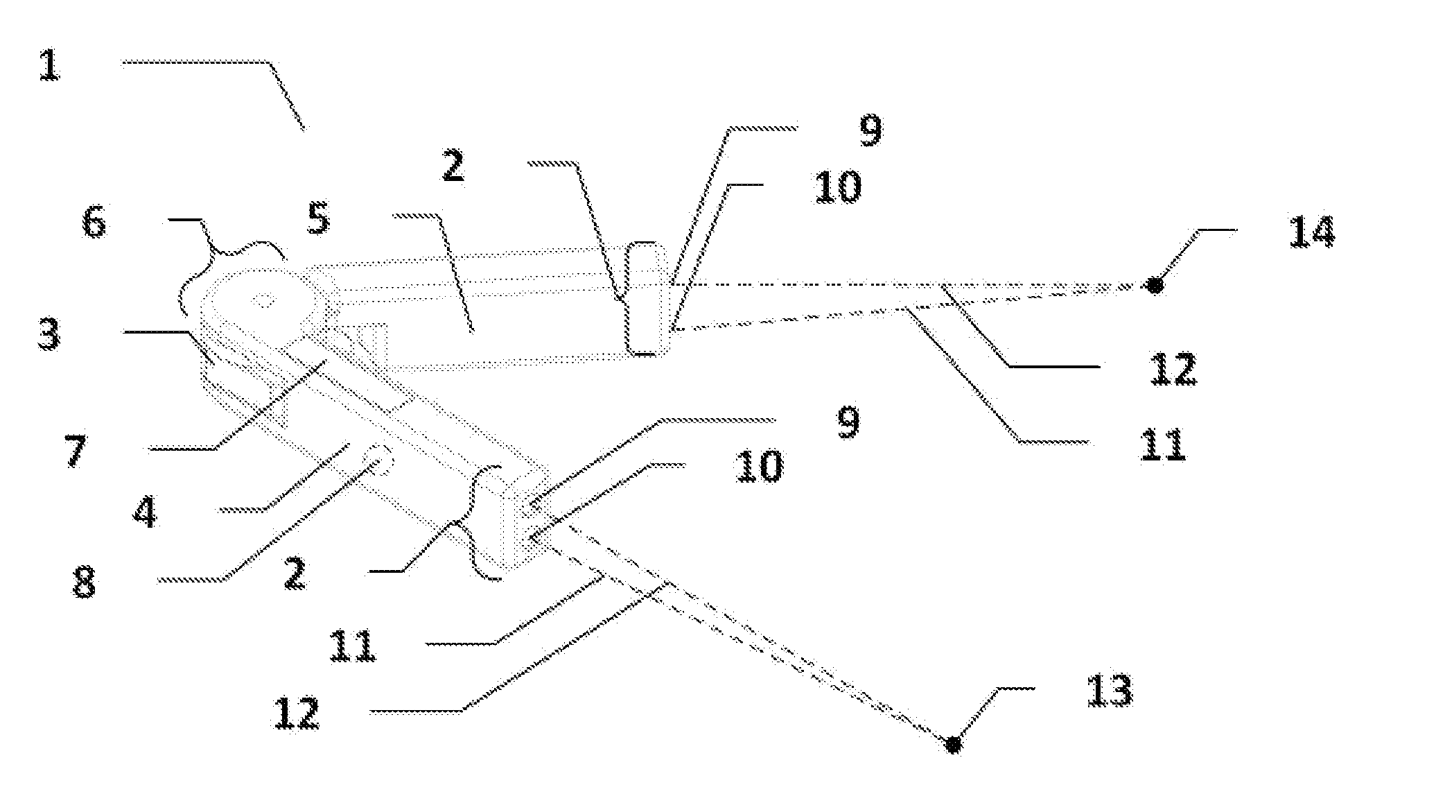
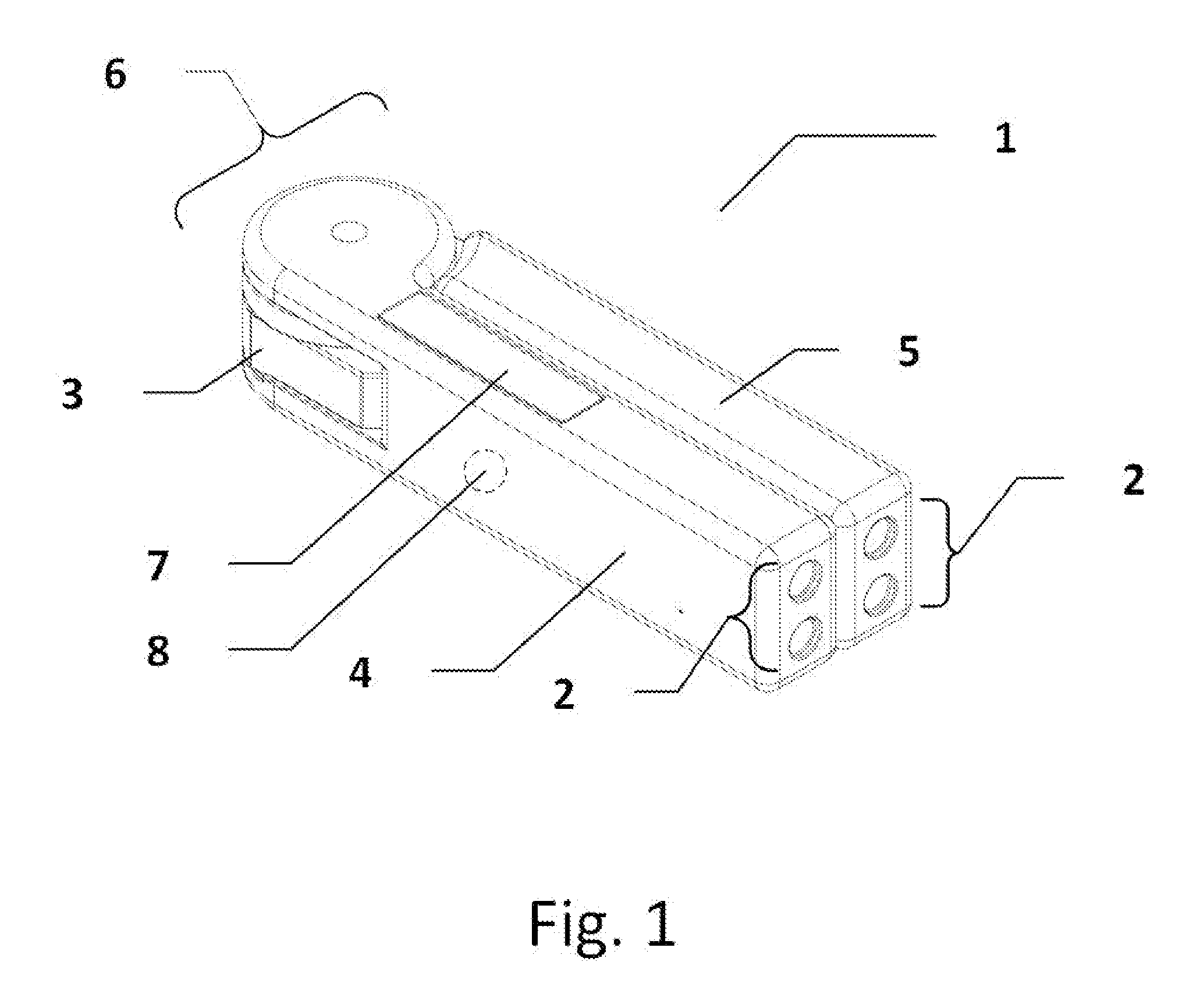
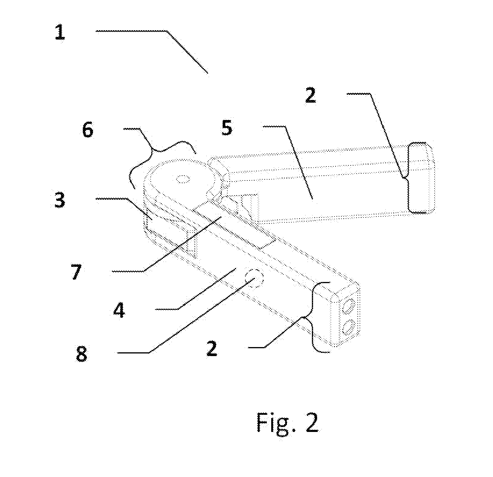
[0024]A system 1 in accordance with an exemplary embodiment of the present invention is illustrated in FIGS. 1-6. Referring to FIGS. 1 and 5, the system 1 generally comprises two distance measurement sensors 2 and an angle measurement sensor 3. Each distance measurement sensor 2 is connected to a hollow enclosure 4 and 5, and the hollow enclosures 4 and 5 are joined by a hinge 6 that is pivotal between 0°, illustrated in FIG. 1, and 180°. While the illustrated embodiment pivots between 0° and 180°, the invention is not limited to such and other ranges may be utilized. The system is ill...


PUM


Abstract

A device for determining the distance between two points on a surface or surfaces in 3-dimensional space, regardless of the orientation of the points relative to the device, provided an unobstructed line-of-sight between the device and both points. The device includes two distance measuring range finders that are joined by a hinge. The hinge includes a rotary encoder for measuring the angular displacement of the two sensors. By utilizing the distance measurements that each range finder relays, as well as the angular displacement measured by the rotary encoder, the microcontroller determines the final length between the two points and displays it through a display screen.

Description

[0001]This application claims the benefit of U.S. Provisional Application No. 62 / 162,890 filed on May 18, 2015, the contents of which are incorporated herein by reference.FIELD OF THE INVENTION[0002]The present invention relates to a system and method for distance measurement. More specifically, the present invention relates to a system and method for finding the distance between two points on any surface or surfaces in 3-dimensional space.BACKGROUND OF THE INVENTION[0003]Laser range finding technology has been widely used in engineering, construction, architecture, and other fields of work that require contactless measurement of spatial relationships. The traditional rangefinder, which is in widespread use, is mainly capable of finding the distance between an arbitrary point and the user.[0004]With the traditional laser rangefinder technology, the user must situate oneself at one of the two points of interest and then proceed to find the distance between oneself and the other point...

Claims


Application Information

Patent Timeline
Patent Type & Authority Applications(United States)
IPC IPC(8): G01B11/14G01C3/08G01D5/26
CPCG01B11/14G01C3/08G01D5/26
Inventor AN, TAE HWISMALL, AUSTIN
Owner AN TAE HWI
Why Eureka
Try Eureka