Whole angle MEMS gyroscope

a gyroscope and whole angle technology, applied in the field of vibration structure gyroscopes, can solve the problems of limited open-loop sense axis, limited rate mode operated gyroscopes, limited coriolis-induced motion measurement, etc., and achieves low damping, high dynamic range, and high sensitivity.

Active Publication Date: 2016-11-24
CHARLES STARK DRAPER LABORATORY
View PDF3 Cites 31 Cited by
  • Summary
  • Abstract
  • Description
  • Claims
  • Application Information

AI Technical Summary

Benefits of technology

[0007]A new MEMS based gyroscope design is provided that combines the best features of a lumped-element TF gyroscope and a rotationally symmetric gyroscope. Certain embodiments efficiently use relatively large masses (e.g., like a TF gyroscope) supported by relatively weak flexures to provide low damping and hence high sensitivity while maintaining an eight-fold symmetry conducive to the n=2 vibratory mode used in most whole angle based gyroscopes to provide high dynamic range. As discussed in more detail below, certain embodiments are capable of operating in both rate and whole angle mode, are low cost, and are easily fabricated.

Problems solved by technology

Rate mode operated gyroscopes are limited in that the Coriolis-induced motion measurements are limited by the dynamic range of the open-loop sense axis.
For fast movements of the gyroscope, the open-loop sense axis may not be able to “keep up” with the movement of the gyroscope.
In addition, spring non-linearities at high rates of rotation may cause errors.
However, such gyroscopes are limited by the closed sense loop bandwidth and the maximum force capable of being exerted by the rebalance.

Method used


Image

  • Whole angle MEMS gyroscope
  • Whole angle MEMS gyroscope
  • Whole angle MEMS gyroscope

Examples


Embodiment Construction

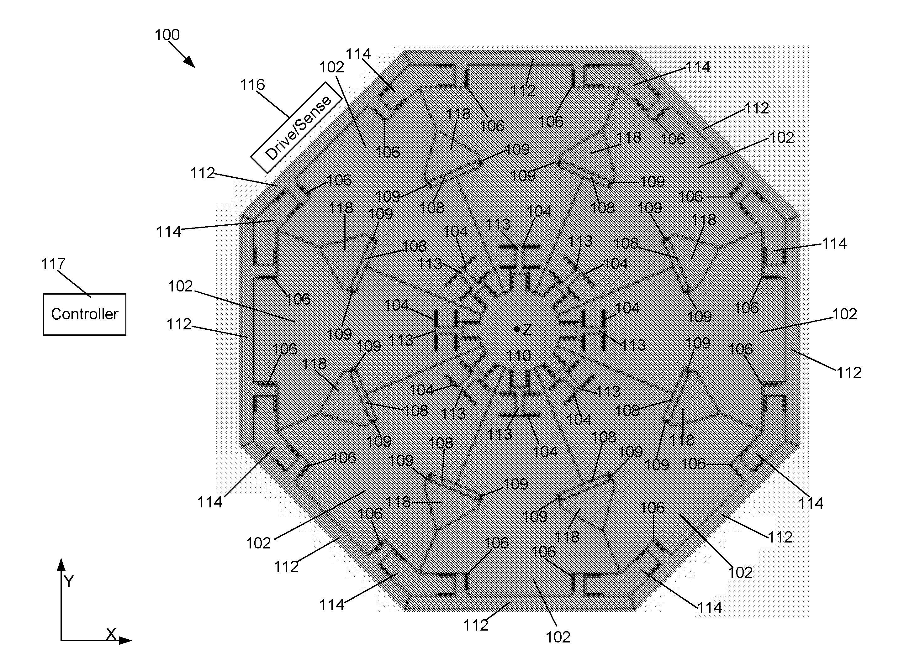
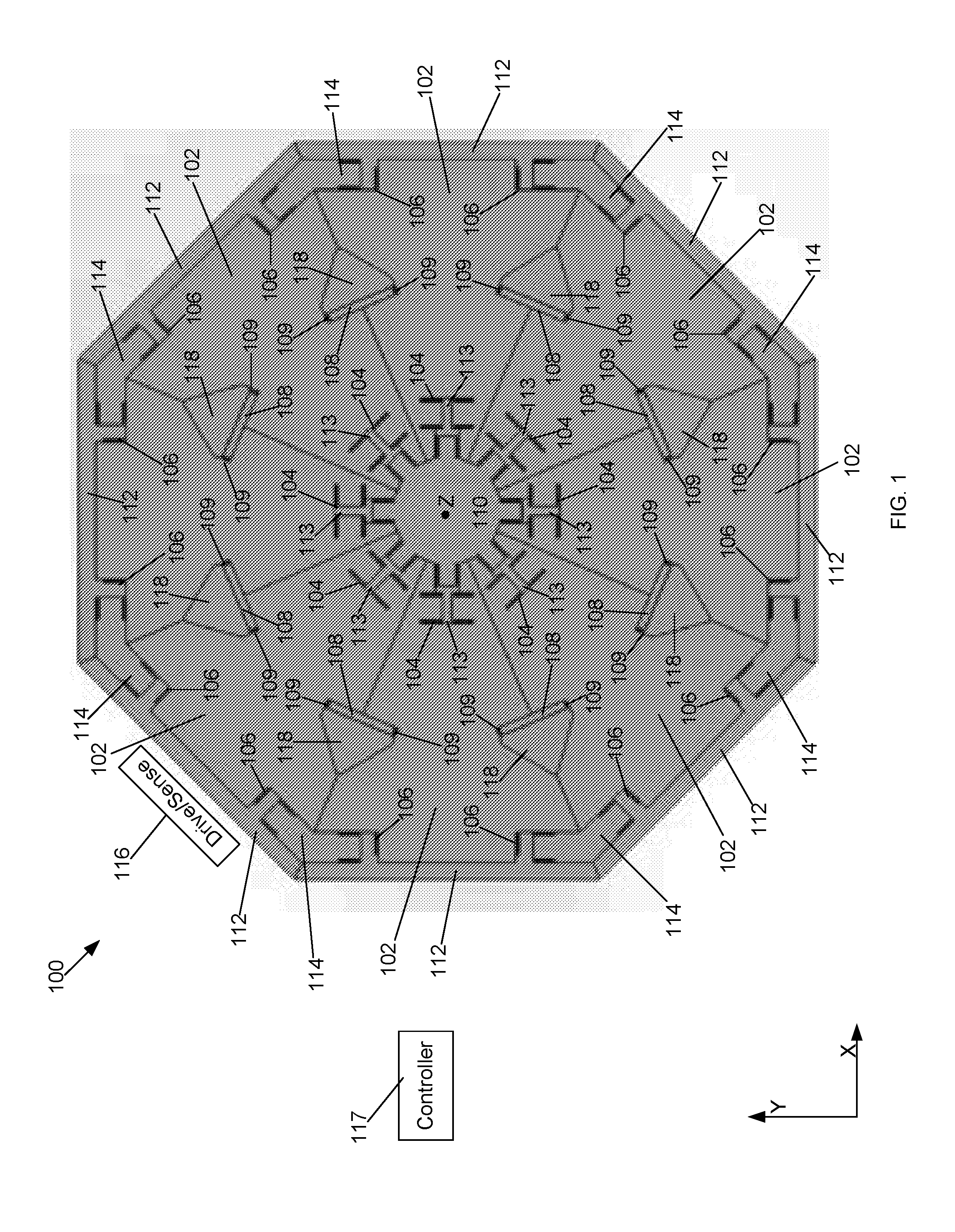
[0051]As discussed above, whole angle operating MEMS based gyroscopes include two axes (i.e., two vibratory modes) coupled by Coriolis motion. In a whole angle operating gyroscope, the axes (i.e., vibratory modes) are driven such that the total vibrational amplitude of the two modes is sustained, but the distribution of energy between the two modes is allowed to change freely. By measuring the distribution of motion between the modes, an angle of rotation of the gyroscope can be read out.

[0052]One important requirement of a whole angle operating MEMS based gyroscope is that the two modes be identical (i.e., degenerate) with regard to frequency and damping. If the frequencies differ substantially, a Coriolis force caused by rotation of the gyroscope will not be sufficient to transfer energy from one mode to the other and the vibration will stay “locked” to a single axis. This will interfere with the free transfer of motion between modes and the free precession of the mode shape of th...


PUM


Abstract

According to one aspect, embodiments herein provide a gyroscope comprising a central anchor, a plurality of internal flexures, a plurality of masses, each mass coupled to the central anchor via at least one of the plurality of internal flexures and configured to translate in a plane of the gyroscope, and a plurality of mass-to-mass couplers, each mass-to-mass coupler coupled between two adjacent masses of the plurality of masses, and a plurality of transducers, each configured to perform at least one of driving and sensing motion of a corresponding one of the plurality of masses, wherein the plurality of transducers is configured to drive the plurality of masses in at least a first vibratory mode and a second vibratory mode.

Description

CROSS-REFERENCE TO RELATED APPLICATIONS[0001]The presented application claims priority under 35 U.S.C. §119(e) to U.S. Provisional Application Ser. No. 62 / 165,365, filed on May 22, 2015, entitled WHOLE ANGLE MEMS GYROSCOPE, which is hereby incorporated herein by reference.BACKGROUND OF THE INVENTION[0002]The present disclosure generally relates to vibrating structure gyroscopes and more specifically to Microelectromechanical System (MEMS) based vibrating structure gyroscopes. Vibrating structure gyroscopes utilize solid-state resonators, of different shapes, to measure orientation or rotation rate based on the principle that a vibrating object tends to continue vibrating (i.e., oscillate) in a fixed orientation in space as its support rotates, and any vibrational deviation of the object can be used to derive a change in direction. Vibrating structure gyroscopes may be manufactured with MEMS based technology. For example, vibrating structure gyroscopes may be fabricated on silicon or...

Claims


Application Information

Patent Timeline
Patent Type & Authority Applications(United States)
IPC IPC(8): G01C19/5726G01C19/5733
CPCG01C19/5733G01C19/5726G01C19/5684
Inventor COOK, EUGENE H.WEINBERG, MARC S.BERNSTEIN, JONATHAN J.
Owner CHARLES STARK DRAPER LABORATORY
Why Eureka
Try Eureka