Optical connector

a technology of optical connectors and connectors, applied in the field of optical connectors, can solve the problems of degrading affecting the quality of the connector, and the application of glue is relatively difficult, and achieves the effect of simple, quick and cost-effective production

Inactive Publication Date: 2009-06-30
MOLEX INC
View PDF16 Cites 2 Cited by
  • Summary
  • Abstract
  • Description
  • Claims
  • Application Information

AI Technical Summary

Benefits of technology

[0017]Therefore, it is an object of the invention to provide an optical connector, which is simple, quick and cost-effective to produce.
[0018]A further object of the invention is to provide an optical connector, which provides an optical connection of high quality, especially with low damping and low reflection.
[0019]A further object of the invention is to provide an optical connector, which is mechanically precise and durable.

Problems solved by technology

It is, however, apparent that this is only a very simple application and there are hardly any limits to multi media networking of on board electronics in order to meet user needs.
In many respects these connectors have disadvantages, since the wave guide sections are very small and therefore glue application is relatively difficult.
Hereby especially the danger of contaminating the sensitive optical contact surfaces of the wave guide exists, which can degrade the quality of the connector to a degree that makes it completely unusable.
Furthermore the longitudinal positioning of the wave guide section in the connector has to be performed with high dimensional accuracy, which is difficult to do with gluing, also.
Furthermore glue application requires a complex machine and the curing of the glue takes rather long, making the connectors rather expensive and mass production difficult.
Now, it has become apparent, that this kind of clamping creates bulges within the optical contact surface of the wave guide section, which can be disadvantageous in several respects.
Firstly, there is the risk that the optical contact surface of the wave guide is distorted so severely that their transfer capabilities are in being influenced negatively.
Thereby in particular undesirable reflections can be created at the optical contact surfaces.
Furthermore the elevation of the bulges is undefined, which makes an exact longitudinal positioning of the wave guide in the connector at least difficult.
Furthermore with the known clamping tips, especially due to their shape there is the danger of damaging the wave guide.
This can make the connector completely unusable in the worst case.

Method used


Image

  • Optical connector
  • Optical connector
  • Optical connector

Examples


Embodiment Construction

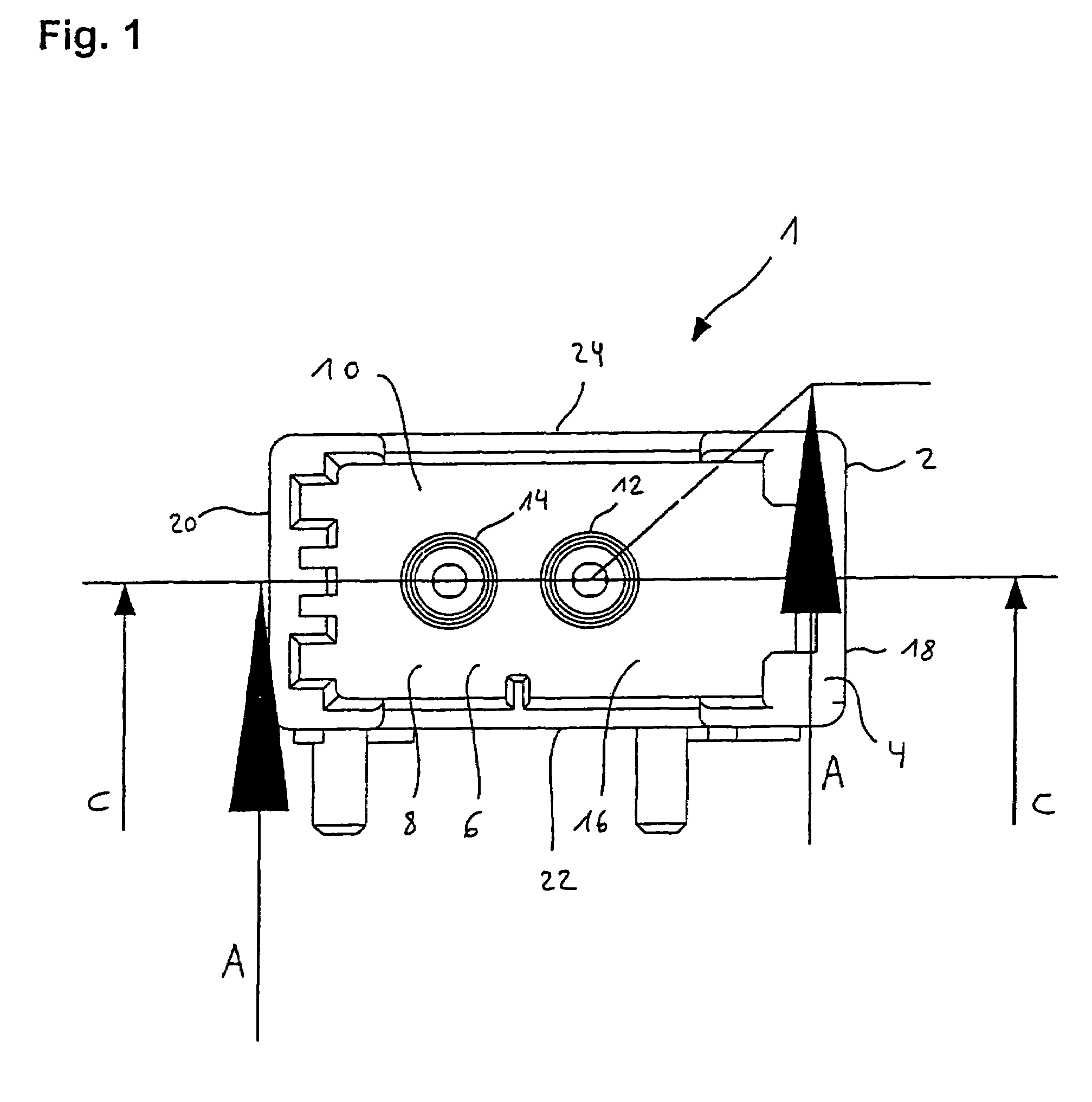
[0072]FIG. 1 shows a connector (1) with a plastic connector housing (2), having an opening (6) on its front (4). The opening (6) provides access to a cavity (8) in the connector housing (2), hereby creating a receptacle (10) for a mating connection with a mating connector (not shown) having a complementary optical terminal element including an optical fiber defining an optical axis.

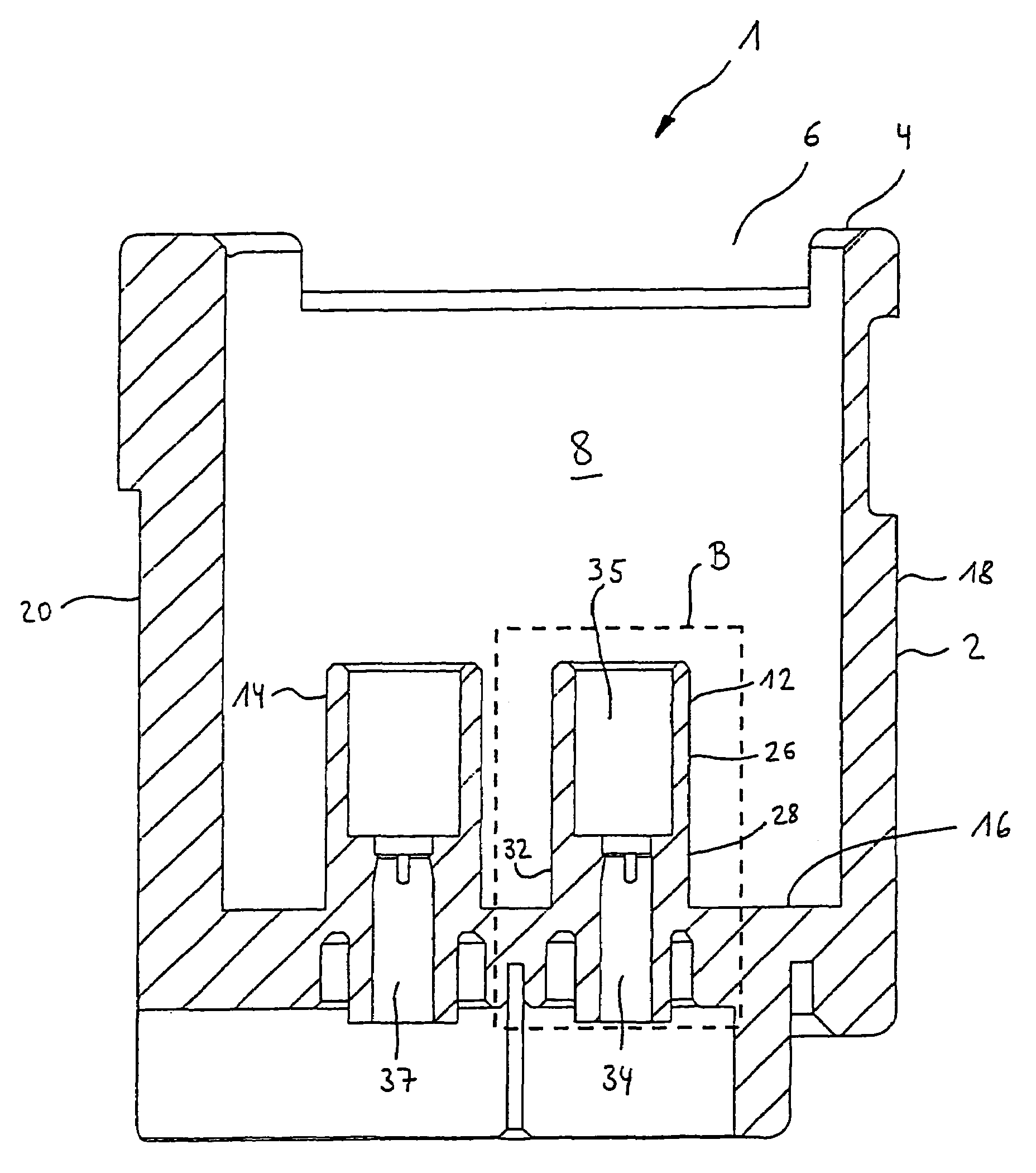
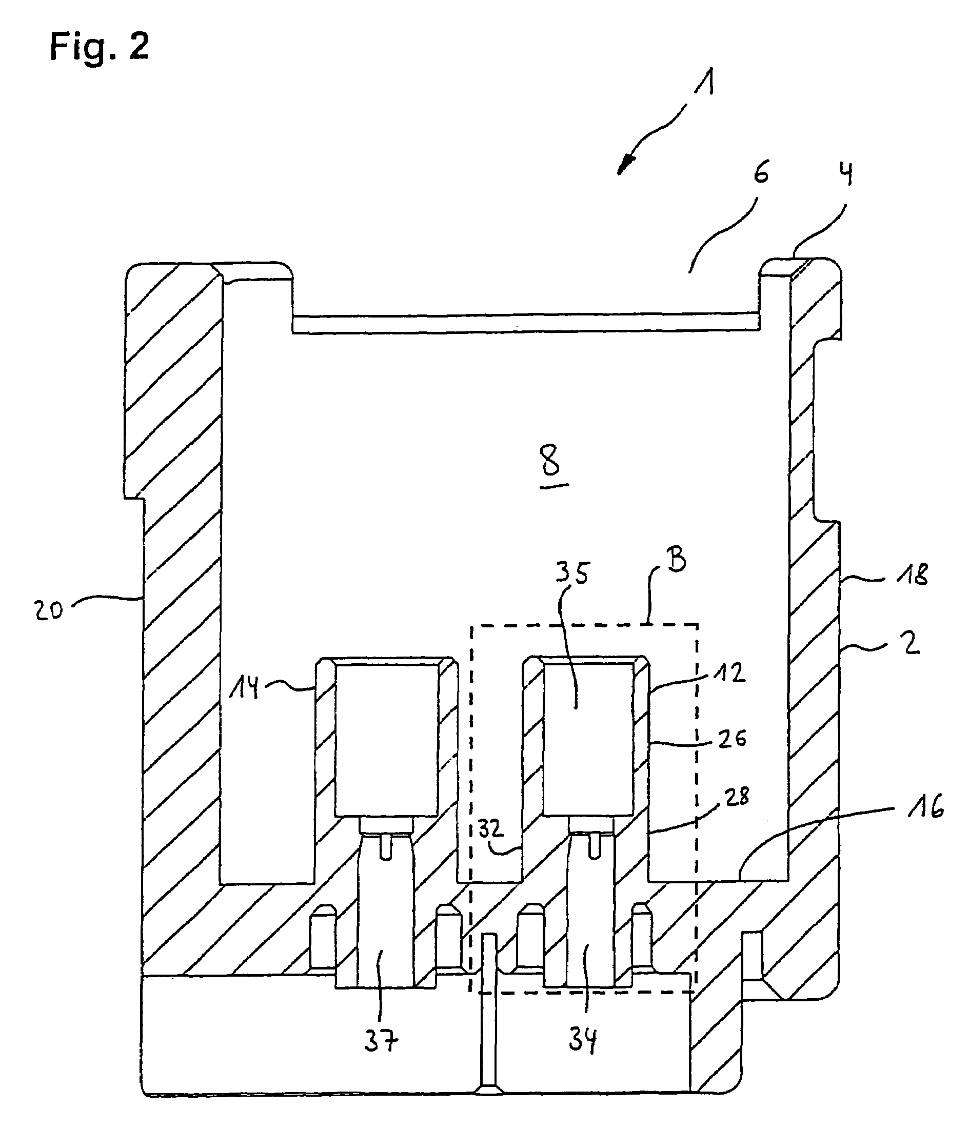
[0073]In the cavity (8) two optical terminal elements (12, 14) are located, which have the form of cylindrical terminal sleeves, which are integrally formed in one piece with the connector housing (2).

[0074]The connector housing (2) is integrally formed in one piece by a front side (4), a rear side (16), two side pieces (18, 20), a bottom (22) and a cover (24).

[0075]With reference to FIG. 2, it is shown in a cross section through the connector housing (2), that the cavity (8) reaches from the front side (4) to the rear side (16) of the connector housing (2). From the rear side (16) the two terminal sleeve...


PUM


Abstract

The invention relates to a connector for establishing multi media connections in vehicles according to MOST®-standard.The objective is to provide an optical connector, which is simple, quick and inexpensive to manufacture, providing an optical connection with low damping, high precision and durability.The MOST-connector comprises at least one optical terminal with a fiber receiving sleeve, wherein the optical fiber section is located, wherein the optical fiber section is affixed directly to the fiber receiving sleeve through clamping elements. According to the invention the fiber receiving sleeve comprises a front side in the area of the front optical contact surface of the optical fiber section, wherein the clamping elements or latching notches are longitudinally spaced from the front side of the fiber receiving sleeve.

Description

FIELD OF THE INVENTION[0001]The invention relates to an optical connector for connecting plastic fibers in general and establishing multi media connections in vehicles e.g. according to MOST®-standard in particular.BACKGROUND OF THE INVENTION[0002]Due to the increasing complexity of applications in the field of vehicle-related information technology, which can be designated as “multi media” today, new concepts for networking various devices are required.[0003]For example at least car radios, mobile phones and navigation systems should be able to communicate with each other in a bidirectional manner, so e.g. the auto radio can be muted and the mobile telephone can be operated through the radio speakers, when the user wants to make a telephone call. It is, however, apparent that this is only a very simple application and there are hardly any limits to multi media networking of on board electronics in order to meet user needs.[0004]In order to meet these complex requirements optical da...

Claims


Application Information

Patent Timeline
Patent Type & Authority Patents(United States)
IPC IPC(8): G02B6/36G02B6/43G02B6/38G02B6/42
CPCG02B6/421G02B6/4292G02B6/3835G02B6/36G02B6/42
Inventor SCHEMPP, OTTOGERNER, MATHIAS
Owner MOLEX INC
Why Eureka
Try Eureka