Solid oxide fuel cell system

a fuel cell and solid oxide technology, applied in the direction of fuel cells, electrochemical generators, electrical equipment, etc., to achieve the effect of preventing a reduction in heat exchange efficiency and reducing cost and siz

Active Publication Date: 2016-11-24
PANASONIC INTELLECTUAL PROPERTY MANAGEMENT CO LTD
View PDF2 Cites 15 Cited by
  • Summary
  • Abstract
  • Description
  • Claims
  • Application Information

AI Technical Summary

Benefits of technology

[0005]However, there is still room to improve the fuel cell system disclosed in Japanese Patent No. 5381239 from the perspective of heat-exchange efficiency, cost, and size. One non-limiting and exemplary embodiment provides a method for operating a solid oxide fuel cell system that can reduce both the cost and the size while preventing a reduction in the heat-exchange efficiency.

Problems solved by technology

However, there is still room to improve the fuel cell system disclosed in Japanese Patent No. 5381239 from the perspective of heat-exchange efficiency, cost, and size.

Method used


Image

  • Solid oxide fuel cell system
  • Solid oxide fuel cell system
  • Solid oxide fuel cell system

Examples


embodiments

[0017]A solid oxide fuel cell system according to a first aspect of the present disclosure includes a solid oxide fuel cell that produces electricity by using a hydrogen-containing gas and an oxidant gas, an exhaust-gas path via which an exhaust gas discharged from the solid oxide fuel cell flows, a circulation path via which a coolant circulates, a first heat exchanger that is disposed on the exhaust-gas path and the circulation path and enables heat exchange between the exhaust gas and the coolant, a first tank that is disposed on the circulation path and stores, as the coolant, condensed water produced when the exhaust gas is cooled by the coolant in the first heat exchanger, and a second heat exchanger that is disposed so as to enable heat exchange between the coolant and reservoir water.

[0018]With this structure, the reservoir water composed mainly of tap water is not used as the coolant, which exchanges heat with the exhaust gas in the first heat exchanger. Accordingly, scale ...

first embodiment

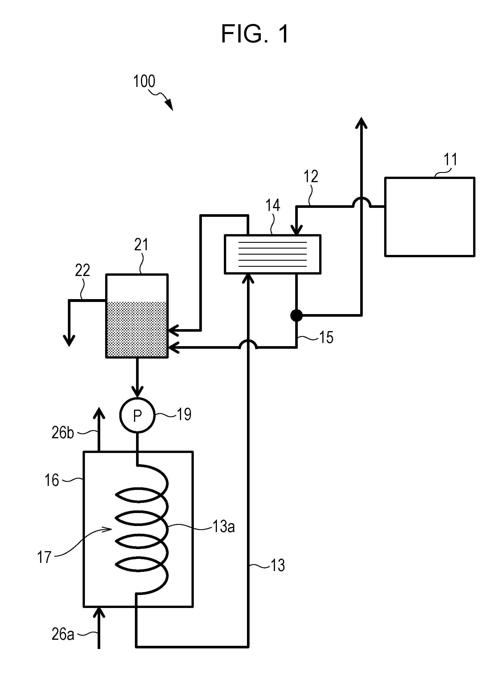
[0028]A solid oxide fuel cell system (SOFC system) 100 according to a first embodiment will be described with reference to FIG. 1. FIG. 1 is a block diagram showing an example of the functional structure of the SOFC system 100 according to the first embodiment. The SOFC system 100 is a solid oxide fuel cell system and includes a solid oxide fuel cell (SOFC) 11, an exhaust-gas path 12, a circulation path 13, a first heat exchanger 14, a first tank 21, and a second heat exchanger 17. The SOFC system 100 may also include a first pump 19 and a second pump 20. The SOFC system 100 may further include a second tank 16, a second path 15, and an overflow path 22.

[0029]The SOFC 11 is a solid oxide fuel cell that produces electricity by using a hydrogen-containing gas and an oxidant gas. The SOFC 11 produces electricity and water by an electrochemical reaction between the hydrogen-containing gas and the oxidant gas in the presence of a catalyst. The SOFC 11 is provided with a cell (not shown),...

second embodiment

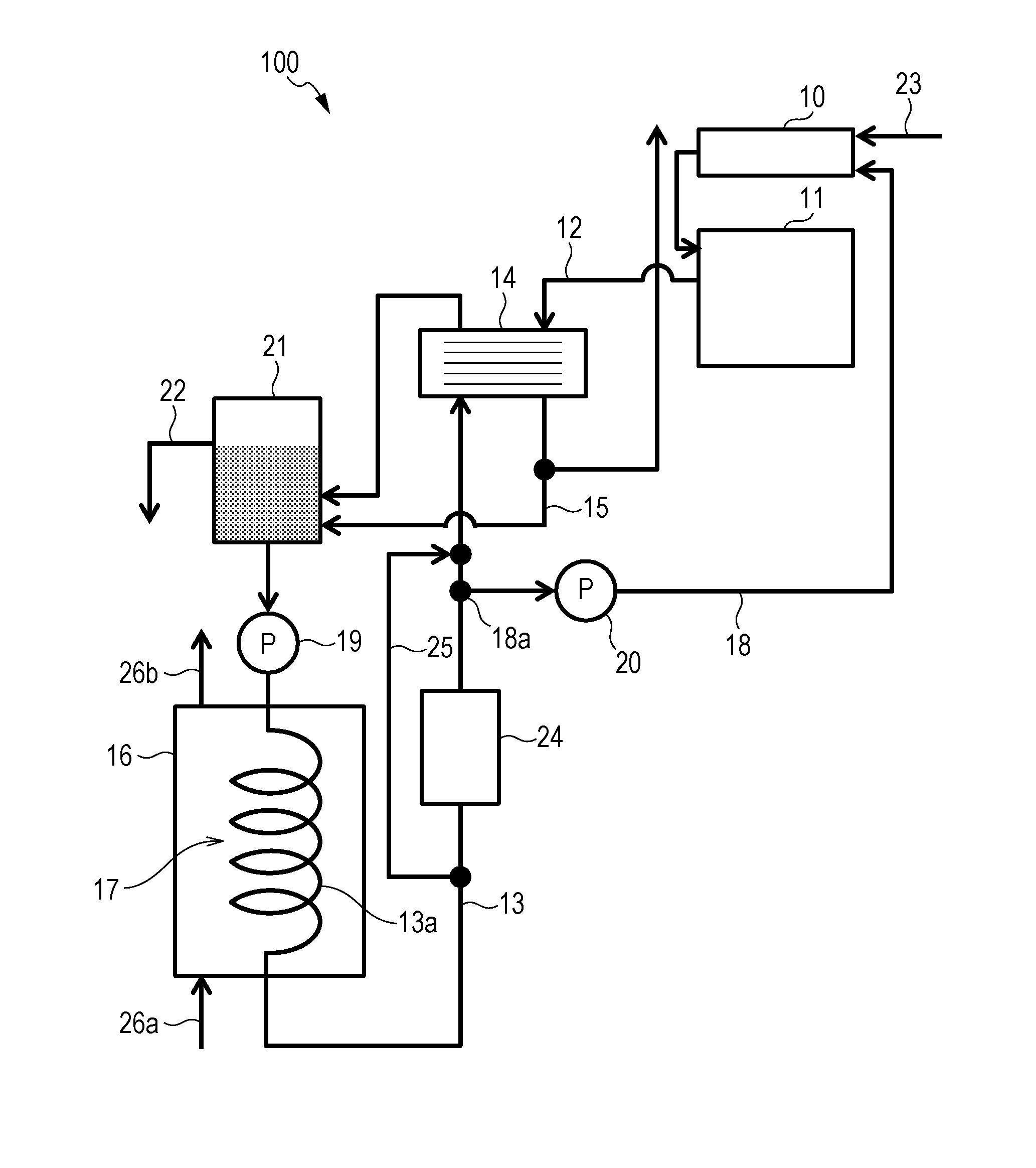
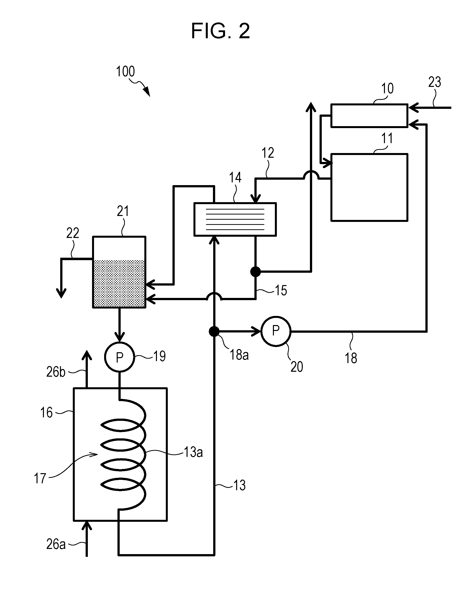
[0045]An SOFC system 100 according to a second embodiment will be described with reference to FIG. 2. FIG. 2 is a block diagram showing an example of the functional structure of the SOFC system 100 according to the second embodiment. The SOFC system 100 further includes a reformer 10 and a first path 18, in addition to the structure in FIG. 1.

[0046]The reformer 10 is a reactor that produces a hydrogen-containing gas by using a source and water (reforming water). The reformer 10 causes a reforming reaction between the source and steam in the presence of a catalyst, producing the hydrogen-containing gas. The reformer 10 is heated to a temperature suitable for the catalyst, for example, a temperature of 600° C. to 700° C. The reformer 10 is provided with an evaporator (not shown), which produces steam from the reforming water supplied via the first path 18. The source is supplied from a source supplier (not shown) to the reformer 10 via a supply path 23. The source is a gas containing ...


PUM

PropertyMeasurementUnit
temperatureaaaaaaaaaa

Abstract

A solid oxide fuel cell system includes a solid oxide fuel cell that produces electricity by using a hydrogen-containing gas and an oxidant gas, an exhaust-gas path via which an exhaust gas discharged from the solid oxide fuel cell flows, a circulation path via which a coolant circulates, a first heat exchanger that is disposed on the exhaust-gas path and the circulation path and enables heat exchange between the exhaust gas and the coolant, a second path, via which condensed water produced when the exhaust gas is cooled in the first heat exchanger flows, that branches from the exhaust-gas path and is connected to the circulation path, a second tank that stores reservoir water, and a second heat exchanger that is disposed in the second tank and on the circulation path and enables heat exchange between the reservoir water and the coolant.

Description

BACKGROUND[0001]1. Technical Field[0002]The present disclosure relates to a solid oxide fuel cell system.[0003]2. Description of the Related Art[0004]An exemplary fuel cell system regarded as a conventional fuel cell system is disclosed in Japanese Patent No. 5381239. In this fuel cell system, a first heat exchanger exchanges heat between flue gas from a fuel cell module and reservoir water from a storage tank. The reservoir water is thus heated by the flue gas and supplied to a drainage system through a circulation line and a drainpipe. The flue gas, on the other hand, is cooled by the reservoir water, so that steam contained in the flue gas is condensed. The condensed water is supplied to a demineralizer through a supply pipe. The demineralized water is supplied to a fuel cell module as reforming water.SUMMARY[0005]However, there is still room to improve the fuel cell system disclosed in Japanese Patent No. 5381239 from the perspective of heat-exchange efficiency, cost, and size. ...

Claims


Application Information

Patent Timeline
Patent Type & Authority Applications(United States)
IPC IPC(8): H01M8/04007H01M8/04029H01M8/1231
CPCH01M8/04067H01M2008/1293H01M8/04029H01M8/1231H01M8/04164H01M8/0618H01M8/04007Y02E60/50
Inventor ISHINO, HISANORITAMURA, YOSHIOYUKIMASA, AKINORIMORITA, JUNJI
Owner PANASONIC INTELLECTUAL PROPERTY MANAGEMENT CO LTD
Why Eureka
Try Eureka