
Aircraft landing light unit, exterior aircraft lighting system and method of operating an aircraft landing light unit

a technology for landing lights and aircraft, applied in electrical equipment, transportation and packaging, lighting and heating equipment, etc., can solve the problems of deterioration of pilot's vision, greatest risk of impairing pilot's vision, and light output that is more likely to be affected by pilot's vision, so as to reduce the light output

Active Publication Date: 2016-11-24
GOODRICH LIGHTING SYST
View PDF5 Cites 9 Cited by
  • Summary
  • Abstract
  • Description
  • Claims
  • Application Information

AI Technical Summary

Benefits of technology

The invention is about a way to prevent a pilot's visibility from being affected during an approach to an airport runway due to reflected light from the landing lights of the aircraft. By controlling the light output of the landing lights based on the reflections by atmospheric haze, the invention reduces the risks to the pilot's vision. By using a single light detection unit and controlling only the landing light unit, the invention is efficient and does not require complex equipment. The method involves detecting the light and controlling the LEDs of the landing light unit accordingly to prevent reflections that may affect the pilot's vision. The facial area is one of the areas that can be affected, so the invention dims a subset of the LEDs to reduce the light output in that area. This technique helps to improve the pilot's vision in conditions of atmospheric haze.

Problems solved by technology

In conditions where the sky and / or the atmosphere around and above the airport runway is not clear, such as in cloudy, foggy, rainy or snowy conditions, generally referred to as atmospheric haze conditions herein, this large amount of light output bears the risk of leading to a deterioration of the pilot's vision due to light reflections from the atmospheric haze.
As aircraft landing lights emit a large amount of light in the pilot's forward vision direction, they present the greatest risk of impairing the pilot's vision due to the reflections from clouds, fog, rain or snow.
In this way, the control unit may reduce the light output from those LEDs that are most prone to causing undesired reflections towards the cockpit, while keeping the illumination by the other LEDs constant.
For example, a lower amount of reflected light may be blinding or disturbing to the pilot in night conditions than during day conditions.

Method used


Image

  • Aircraft landing light unit, exterior aircraft lighting system and method of operating an aircraft landing light unit
  • Aircraft landing light unit, exterior aircraft lighting system and method of operating an aircraft landing light unit
  • Aircraft landing light unit, exterior aircraft lighting system and method of operating an aircraft landing light unit

Examples


Embodiment Construction

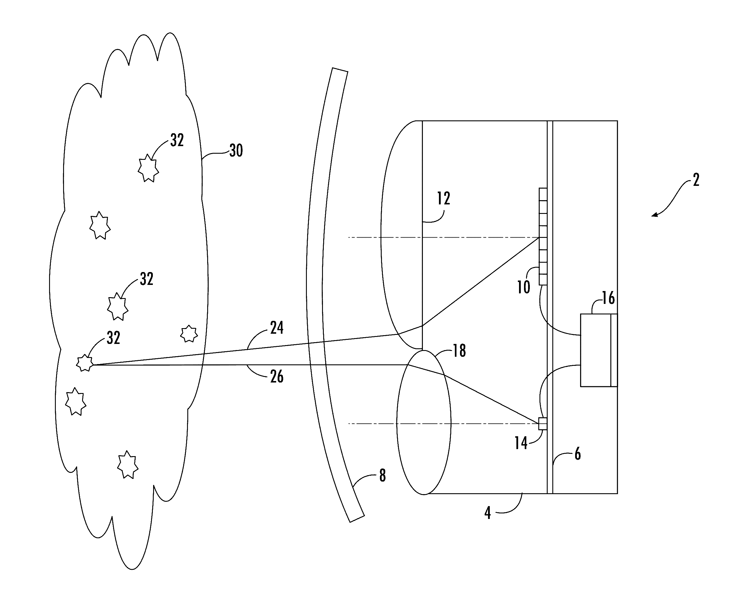
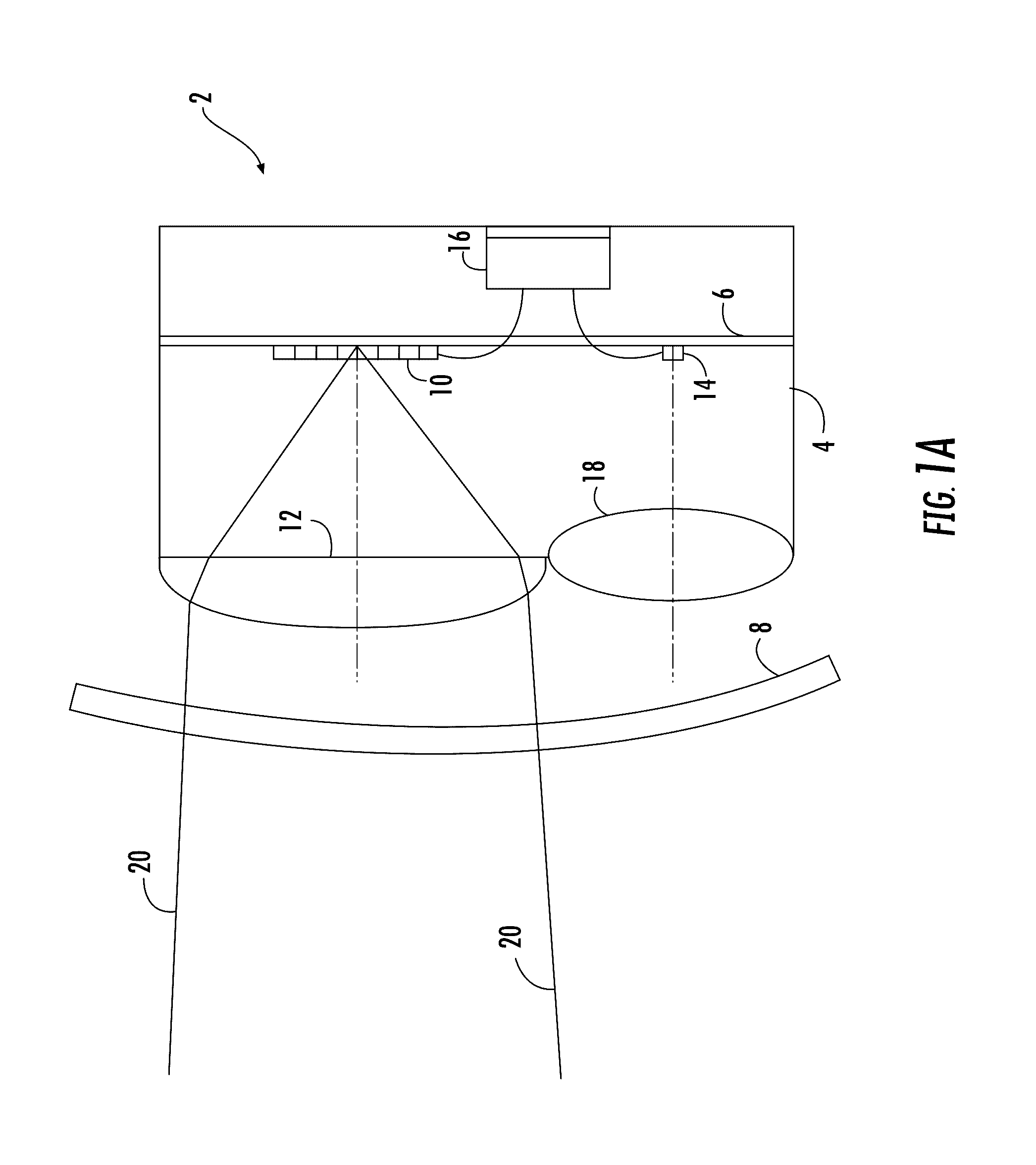
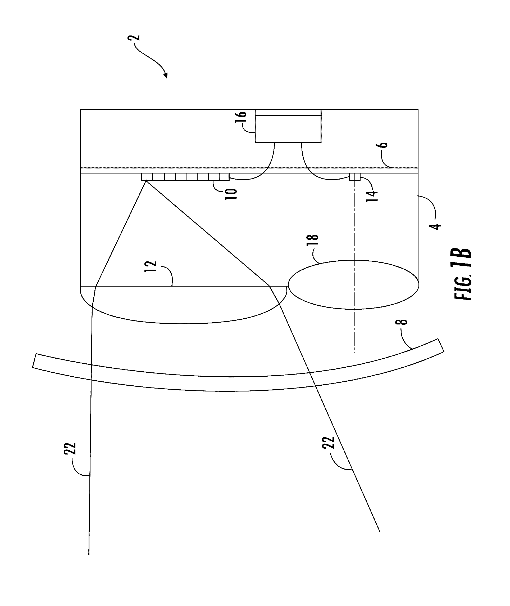
[0034]FIG. 1a shows an exemplary embodiment of an aircraft landing light unit 2 in accordance with the invention. The aircraft landing light unit 2 is shown in a cross-sectional, schematic view in the exemplary embodiment of FIG. 1a. The aircraft landing light unit 2 comprises a housing 4 and a mounting plate 6, to which most of the other elements of the aircraft landing light unit 2 are mounted. The mounting plate 6 is disposed within the interior of the housing 4. The aircraft landing light unit 2 further comprises a lens cover 8, which forms the outermost portion of the aircraft landing light unit 2 and through which the aircraft landing light unit 2 emits light.

[0035]The aircraft landing light unit 2 comprises a plurality of LEDs 10. In particular, the plurality of LEDs 10 are an array of LEDs. Further in particular, the array of LEDs is a two-dimensional array having a regular arrangement of LEDs 10, for example a grid-like arrangement of LEDs. In the schematic cross-sectional ...


PUM


Abstract

An aircraft landing light unit includes a plurality of LEDs, an optical system associated with the plurality of LEDs for shaping a light output of the aircraft landing light unit for illuminating an aircraft environment, a control unit for controlling the plurality of LEDs, and a photo detector arranged for detecting light, emitted by the plurality of LEDs, output via the optical system and reflected by atmospheric haze, such as clouds, fog, rain and snow, wherein the control unit is coupled to the photo detector and is configured to control the plurality of LEDs on the basis of the light detected by the photo detector, thereby adjusting the light output of the aircraft landing light unit to the atmospheric haze.

Description

[0001]FOREIGN PRIORITY[0002]This application claims priority to European Patent Application No. 15 168 342.2 filed May 20, 2015, the entire contents of which is incorporated herein by reference.TECHNICAL FIELD[0003]The present invention is in the field of exterior aircraft lighting. In particular, the present invention is in the field of aircraft landing lights and exterior aircraft lighting systems having such aircraft landing lights coupled to other light units.BACKGROUND OF THE INVENTION[0004]Almost all aircraft are equipped with exterior lights. For example, large passenger air planes have a wide variety of exterior lights. Examples are navigation lights or position lights, beacon lights, anti-collision lights or strobe lights, wing lights, taxi lights, landing lights, runway turnoff lights, etc. These lights provide for various kinds of illumination around the air plane. In particular, during a runway approach, a large number of exterior lights is commonly in operation, such as...

Claims


Application Information

Patent Timeline
IPC IPC(8): H05B33/08H05B37/02F21V5/04B64D47/04B64D47/06H05B44/00
CPCH05B33/0854B64D47/04F21Y2101/02F21V5/04H05B37/0218B64D47/06B60Q1/1423H05B45/10B64D45/08B64D2203/00F21Y2101/00H05B47/11Y02B20/40H05B45/12
Inventor HESSLING-VON HEIMENDAHL, ANDRESCHOEN, CHRISTIANJHA, ANIL KUMAR
Owner GOODRICH LIGHTING SYST
Learn More