Bone screw assembly

Active Publication Date: 2016-12-01
IGNITE CONCEPTS
View PDF26 Cites 1 Cited by
  • Summary
  • Abstract
  • Description
  • Claims
  • Application Information

AI Technical Summary

Benefits of technology

[0011]Therefore, it is an object of the present invention to provide a screw assembly which with

Problems solved by technology

In the case where both external screw threads have a different lead length, a rotational moment may cause the bone screw assembly to slightly turn, however, as both bone screw elements travel a different distance per turn due to the differing

Method used


Image

  • Bone screw assembly
  • Bone screw assembly
  • Bone screw assembly

Examples


Embodiment Construction

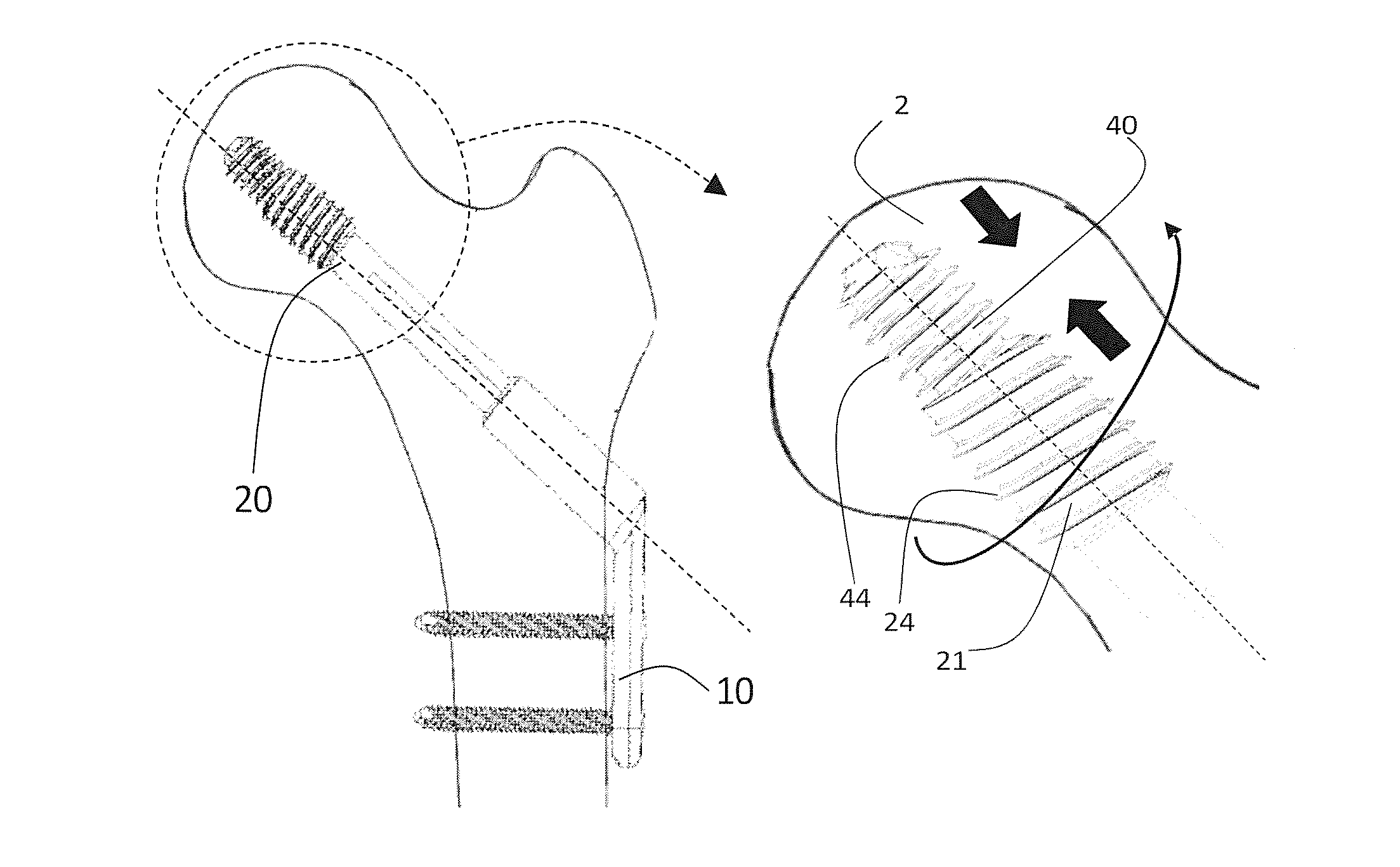
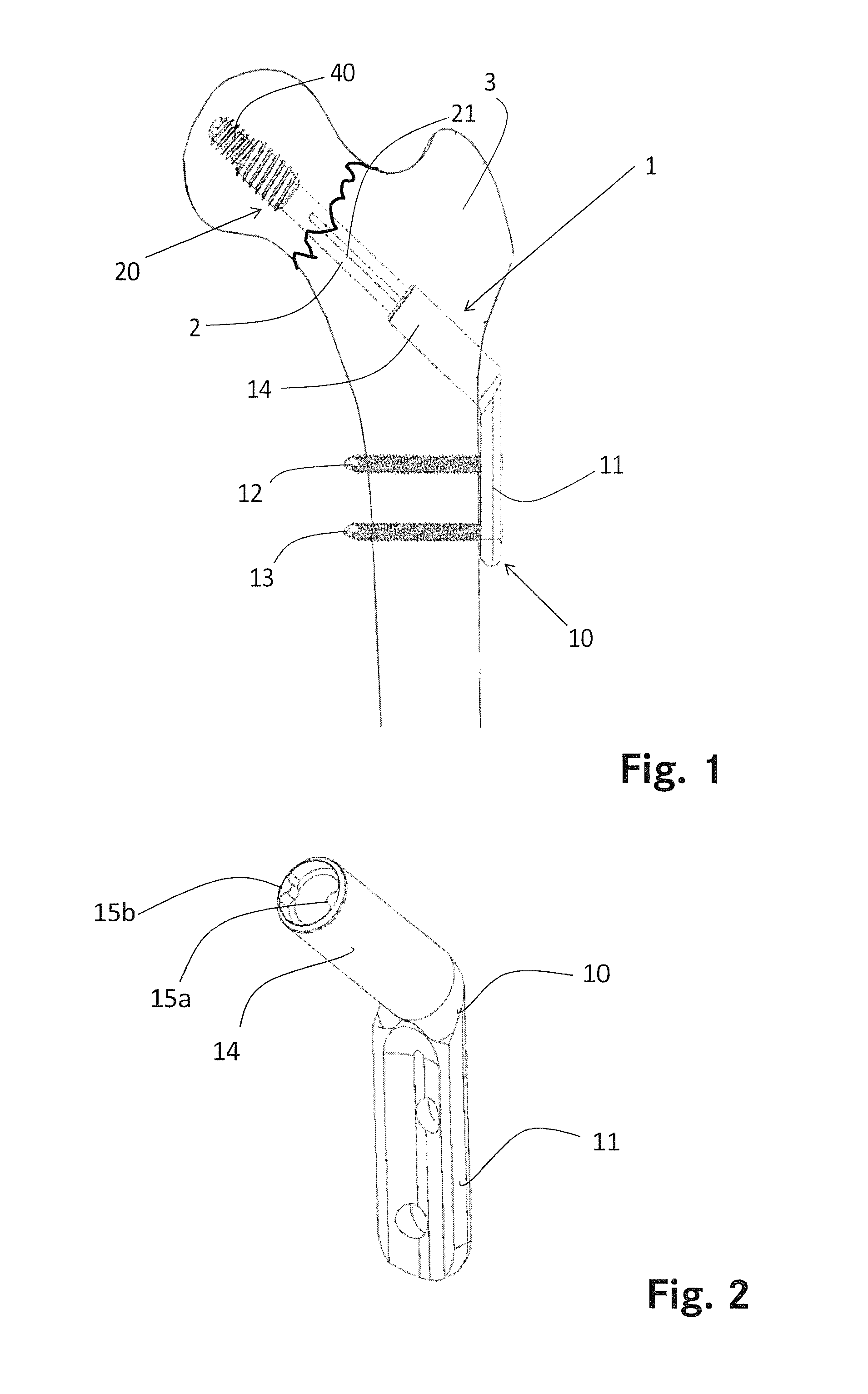
[0064]In reference to FIG. 1 a first embodiment of a bone fixation assembly 1 is shown, bridging a femoral neck fracture. The bone fixation assembly comprises a bone plate 10, a first bone fastener 12 and a second bone fastener 13 and a bone screw assembly 20. The bone plate 10 is attached to the lateral side of femoral shaft 3. The bone screw assembly 20 extends from the bone plate 10 through the femur into the femoral head fragment 2. By bridging the fracture area 4, the bone screw assembly fixates the femoral head fragment 2 to the femoral shaft 3.

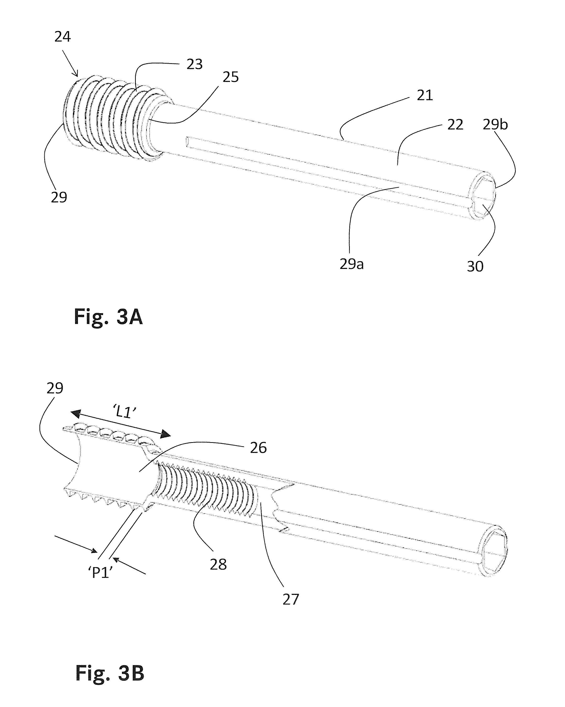
[0065]The bone screw assembly 20 consist of a first bone screw element 21 and a second bone screw element 40, as explained in greater detail below. The bone screw assembly 20 is slidingly engaged into the bone plate 10.

[0066]FIG. 2 shows the bone plate 10. The bone plate 10 comprises a first, flat plate portion 11 for fixation against a femoral bone by using a first bone fastener 12 and a second bone fastener 13. The number of bone fast...


PUM


Abstract

The application relates to a bone screw assembly for fixation into a bone, comprising a first screw element with a body including a threaded first end with a first external screw thread having a first handedness and a first lead length. The first screw element comprises an internal thread feature with a second handedness and a second lead length located within a bore within said body. The screw assembly includes a second screw element comprising a second external screw thread with the second handedness and the second lead length. Said second screw element is arranged within said bore and said second external screw thread is engaged with said internal thread feature. The second screw element is movable from a first implantation configuration where the second screw element is arranged completely within said bore and a second implantation configuration where the second screw element protrudes from said bore.

Description

TECHNICAL FIELD[0001]The present invention relates to a bone screw assembly which withstands rotational moments.BACKGROUND ART[0002]Various bone screws are known in the field. For the stabilisation of a bone fragment multiple screws are normally used to fix the bone fragment to a bone. If only one screw is inserted, the bone fragment could rotate around the axis of the screw and would therefore not exhibit the necessary stability. However, in many indications only one screw may be placed into the bone fragment. For example, in femoral head fractures, only one screw may be used to fixate the femoral head to the femoral shaft. However, when using a single screw, there is a risk that the femoral head rotates around the screw axis, thereby losing the fracture reduction.[0003]Hip fractures are a common injury. The number of annual hip fractures is increasing worldwide. Especially the elderly population suffers from hip fractures. Due to the increasing number of elderly people, the annual...

Claims


Application Information

Patent Timeline
IPC IPC(8): A61B17/86A61B17/74
CPCA61B17/8685A61B17/744A61B17/746A61B17/74
Inventor OVERES, TOM
Owner IGNITE CONCEPTS
Why Eureka
Try Eureka