
Rotational Tool Bit

a tool bit and rotational technology, applied in the direction of screwdrivers, power-driven tools, wrenches, etc., can solve the problems of low torque load they could provide before cam-out, limited amount of torque that could be applied, dangerous situations, etc., to achieve the effect of reducing the amount of cam-out force and high torque load

Inactive Publication Date: 2016-12-01
PINCKARD DANIEL L
View PDF5 Cites 0 Cited by
  • Summary
  • Abstract
  • Description
  • Claims
  • Application Information

AI Technical Summary

Benefits of technology

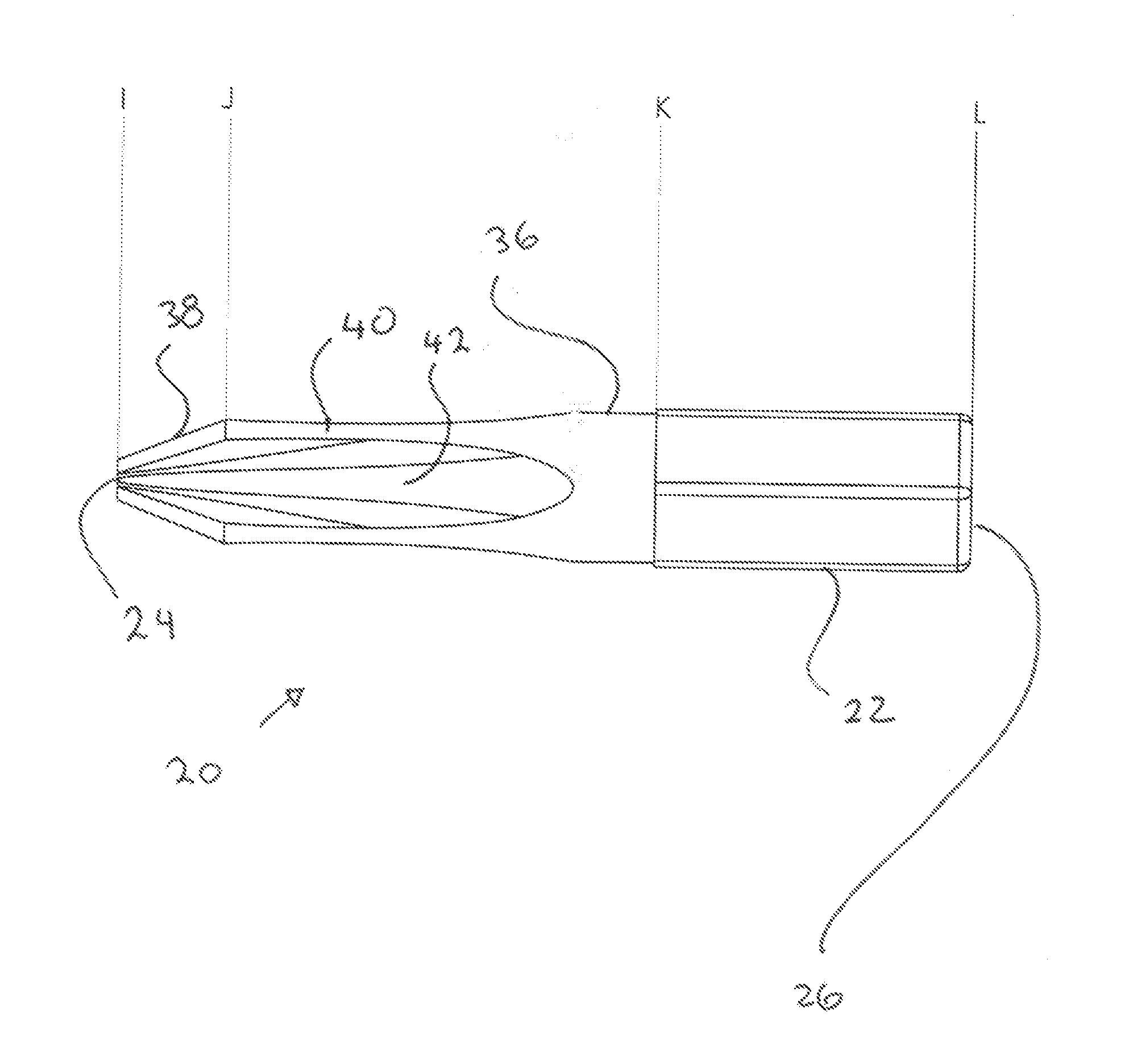
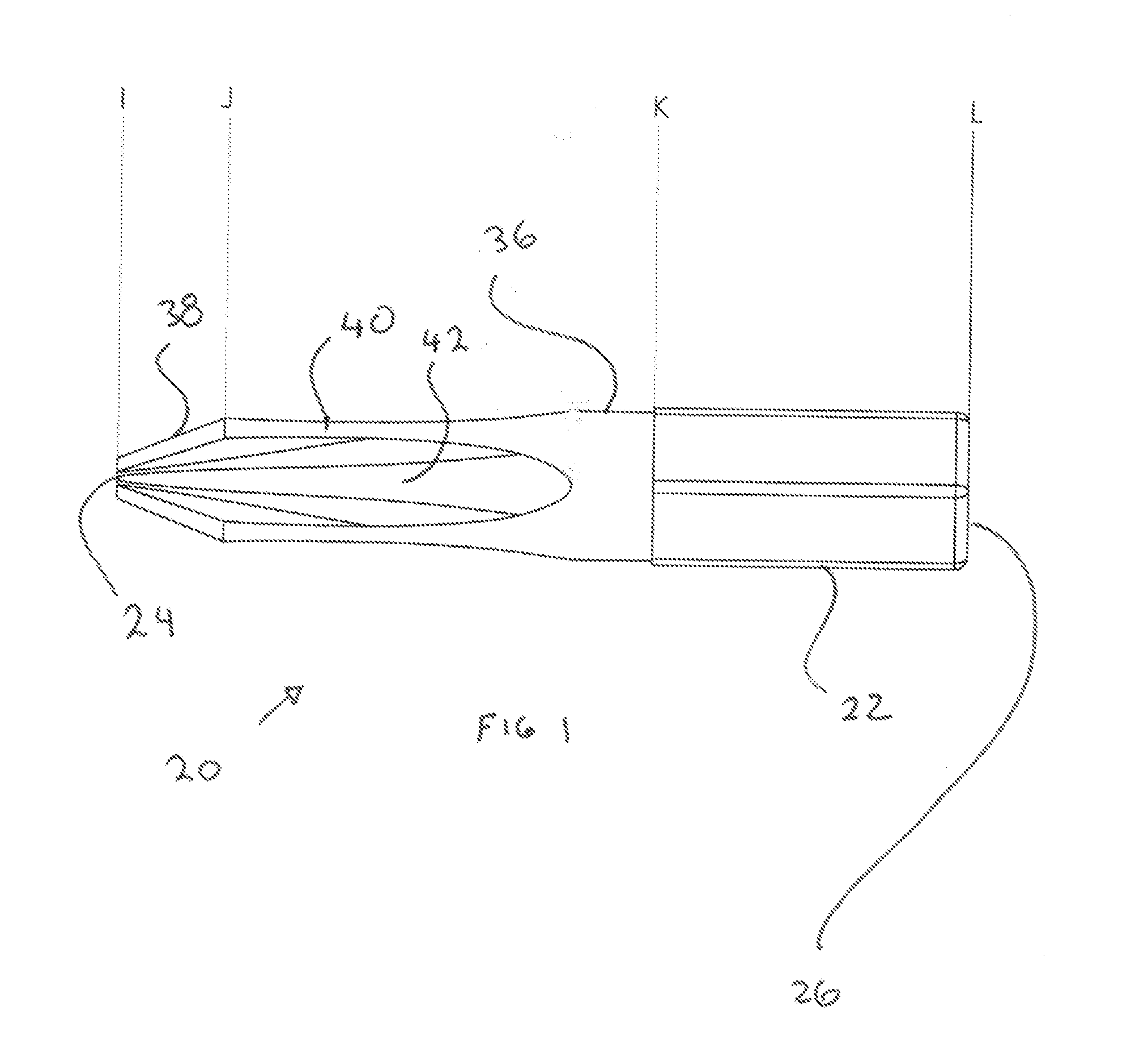
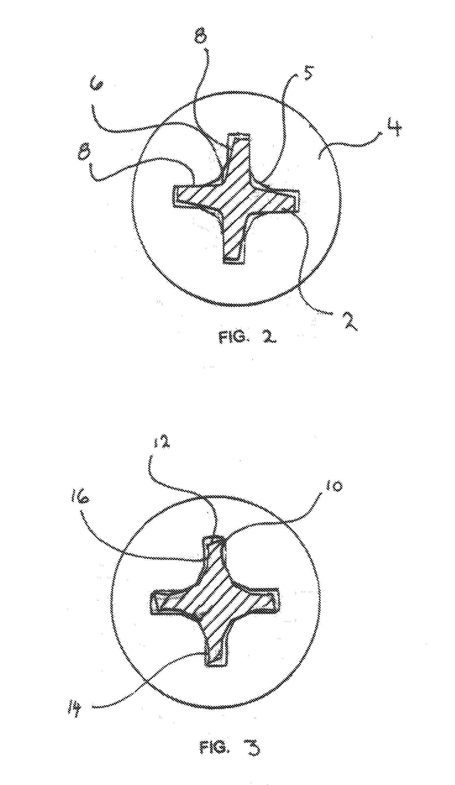
The present invention provides a driver bit for a Phillips style fastener that can handle higher torque loads without stripping or damaging the fastener head. Additionally, the invention includes a mechanism to reduce the cam-out force that drives the bit out of the fastener head. This new rotational tool bit has many advantages and innovative features that make it distinct and different from previous tools on the market.

Problems solved by technology

Unfortunately, for automated screwdrivers on assembly lines, the torque loads they could provide before cam-out were low.
Additionally, the slip out encountered by slotted bits lead to dangerous situations.
First, the amount of torque that could be applied was limited to the amount of contact force the user could maintain between the bit and the fastener, in opposition to the cam-out forces.

Method used


Image

  • Rotational Tool Bit
  • Rotational Tool Bit
  • Rotational Tool Bit

Examples


Embodiment Construction

[0023]There has thus been outlined, rather broadly, the more important features of the invention in order that the detailed description thereof that follows may be better understood and in order that the present contribution to the art may be better appreciated. There are, of course, additional features of the invention that will be described hereinafter and which will form the subject matter of the claims appended hereto.

[0024]In this respect, before explaining at least one embodiment of the invention in detail, it is to be understood that the invention is not limited in its application to the details of construction and to the arrangements of the components set forth in the following description or illustrated in the drawings. The invention is capable of other embodiments and of being practiced and carried out in various ways. Also, it is to be understood that the phraseology and terminology employed herein are for the purpose of descriptions and should not be regarded as limiting...


PUM


Abstract

An improved rotational tool bit used for operational engagement with a Phillips head style fastener that has two points formed at the end of each of its four symmetrical wings and two concave side wall faces on the wing. The points can bite into the fastener and reduce the cam out effect. The design of each of the four wings places the thickest section of the wing behind the two points, aligned facing the reactionary force generated by the torque applied in rotating the fastener so as to prevent deformation of the points under load.

Description

[0001]The present invention relates to an improved driver bit for enabling rotational engagement of a mechanical fastener. More particularly, for use with mechanical fasteners that use Phillips style heads. This bit is adapted to provide both safety, enhanced workability and convenience for the user.BACKGROUND OF THE INVENTION[0002]The Phillips style heads of mechanical fasteners were originally developed to simplify production assembly. At the time of their development, slotted head fasteners were the norm. Unfortunately, for automated screwdrivers on assembly lines, the torque loads they could provide before cam-out were low. Additionally, the slip out encountered by slotted bits lead to dangerous situations. Besides providing an instant feel of correct fitting engagement, the four symmetrical wing design of Phillips style driver bits provided the following main mechanical features: the automatic centering of the bit into the fastener's top recess; the ability for the bit to hold ...

Claims


Application Information

Patent Timeline
Patent Type & Authority Applications(United States)
IPC IPC(8): B25B15/00B25B21/02
CPCB25B21/023B25B15/005B25B23/108
Inventor PINCKARD, DANIEL L.
Owner PINCKARD DANIEL L
Learn More