Tire sealant dispensing device

Inactive Publication Date: 2016-12-01
BETO ENG & MARKETING
View PDF1 Cites 2 Cited by
  • Summary
  • Abstract
  • Description
  • Claims
  • Application Information

AI Technical Summary

Benefits of technology

[0008]The primary objective of the present invention is to provide a tire sealant dispensing device including an improved and simplified tire repairing container for quickl

Problems solved by technology

However, the pressure tight container and the pressurized air cartridge are coupled together with a shut off valve, a gas outlet, a gas inlet and may not be easily disengaged from each other, and an outlet valve and an additional riser tube are further required to be attached or mounted to the upper portion of the pressure tight container for allowing the sealant to be selectively supplied to seal and inflate the inflatable objects, but may

Method used


Image

  • Tire sealant dispensing device
  • Tire sealant dispensing device
  • Tire sealant dispensing device

Examples


Embodiment Construction

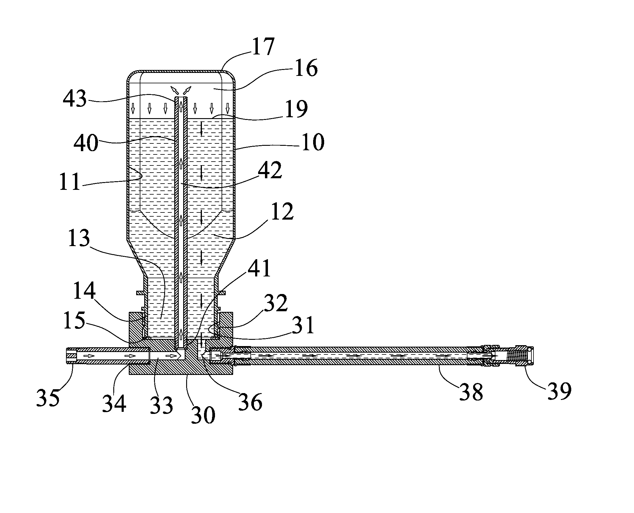
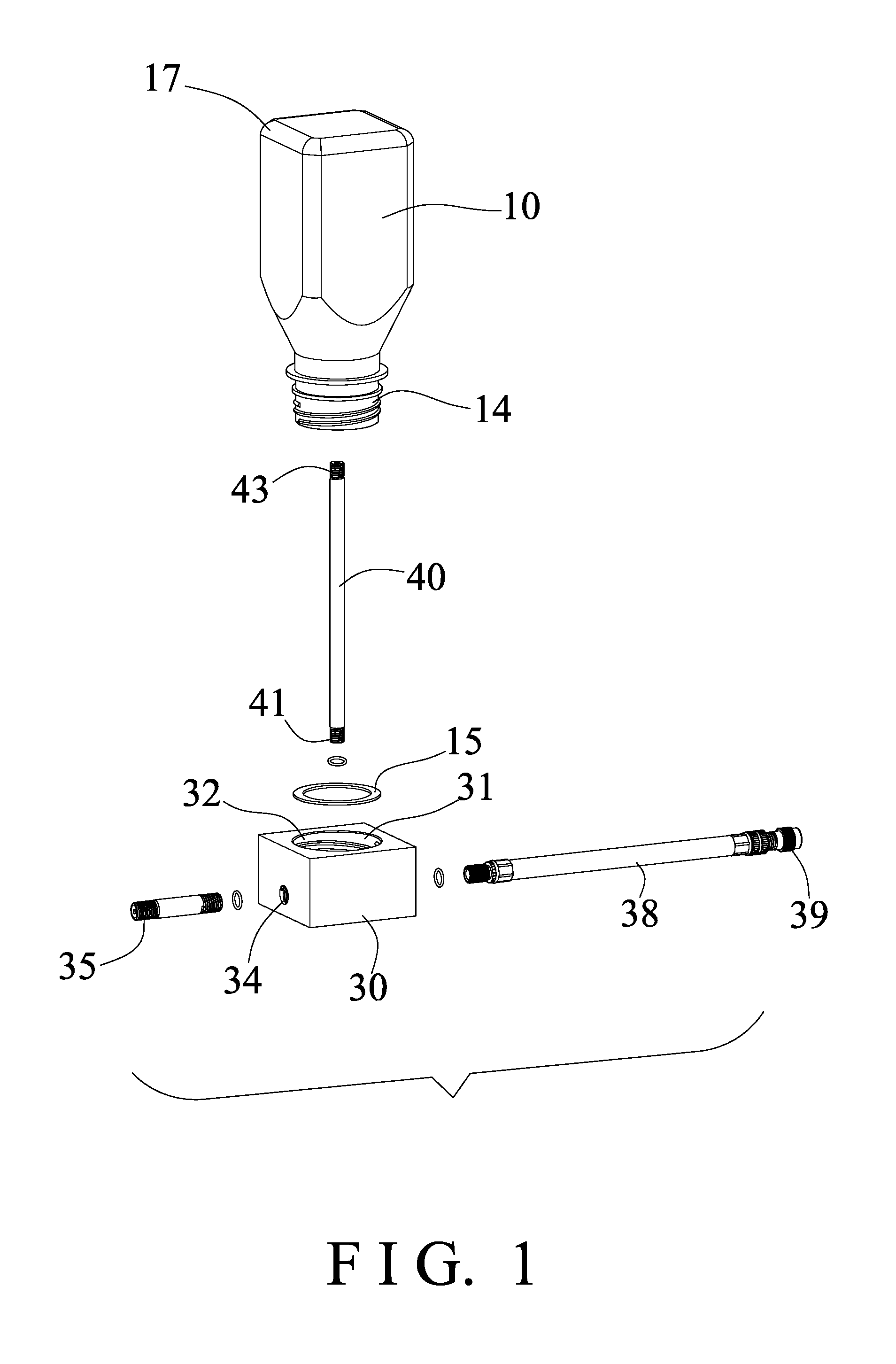
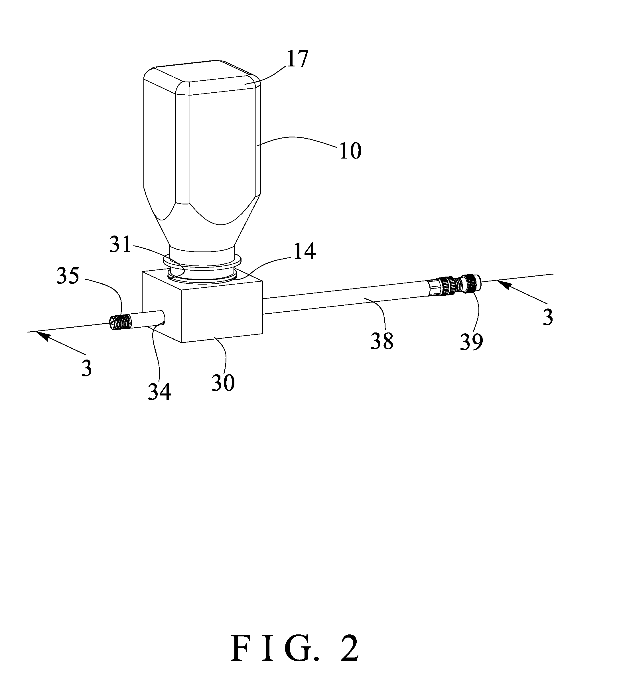
[0017]Referring to the drawings, and initially to FIGS. 1-3, a tire sealant dispensing device in accordance with the present invention comprises a tire repairing container 10 provided and including a compartment or chamber 11 formed therein (FIGS. 3-4) for receiving or engaging a sealing preparation or sealant 12 and for selectively supplying the sealant 12 to seal and inflate the inflatable objects (not illustrated), such as vehicle tires, balls, air beds, air cushions, hovercrafts, etc., and including an opening or mouth 13 formed or provided on the upper or lower portion of the tire repairing container 10 (FIGS. 1 and 3-4) for filling or discharging the sealant 12 into or from the chamber 11 of the tire repairing container 10. The tire repairing container 10 may further include an outer thread 14 formed on the outer peripheral portion of the mouth 13 and / or the upper or lower portion of the tire repairing container 10.

[0018]The tire repairing container 10 further includes an outl...


PUM


Abstract

A tire sealant dispensing device includes a tire repairing container for receiving a sealant, a casing attached to a mouth of the tire repairing container and having an inlet conduit and an outlet conduit, a pipe is disposed in the container and includes one end coupled to the casing and includes a bore for directing the pressurized air to flow through the bore of the pipe and to flow into a base portion of the container without flowing through the sealant, for allowing the tire sealant to be effectively supplied out through the outlet conduit of the casing and to seal and inflate the inflatable objects.

Description

BACKGROUND OF THE INVENTION[0001]1. Field of the Invention[0002]The present invention relates to a tire sealing and inflating assembly for sealing and inflating an inflatable object, and more particularly to a tire sealant dispensing device including an improved and simplified tire repairing container for quickly coupling and attaching and securing to a pressurized air reservoir and for allowing the tire sealant to be effectively supplied to seal and inflate the inflatable objects.[0003]2. Description of the Prior Art[0004]Various kinds of typical air compressing devices have been developed and comprise a cylinder housing, a piston slidably received in the cylinder housing and actuated with a motor in a reciprocating action, in order to generate a pressurized air of a greater air pressure and a decreased flowing quantity, and a pressure tight container for receiving a sealant and for selectively supplying the sealant to seal and inflate the inflatable objects, such as vehicle tires,...

Claims


Application Information

Patent Timeline
IPC IPC(8): B29C73/16B60S5/04B29C73/02
CPCB29C73/166B60S5/04B29C73/025B60C29/062B60C29/06
Inventor WANG, LO PIN
Owner BETO ENG & MARKETING
Why Eureka
Try Eureka