Cleaning module-integrated beverage dispensing head

Active Publication Date: 2018-12-20
INTELLECTUAL DISCOVERY CO LTD
View PDF5 Cites 2 Cited by
  • Summary
  • Abstract
  • Description
  • Claims
  • Application Information

AI Technical Summary

Benefits of technology

[0035]According to some embodiments of the present disclosure, slime, e.g. scales generated in various industrial conduits through which liquid flows, and bacteria deposits on various tubes and the like can be effectively removed by providing a user with an integrated beverage dispensing head capable of selectively providing a cleaning function in addition to conventional beverage dispensing functions.
[0036]Further, according to some embodiments of the present disclosure, water accompanied by pulsation phenomenon or surging can be used for providing sterilizati

Problems solved by technology

Specifically, when various liquid foods and beverages flow along the conduit for a long time, corrosion occurs on the inner surface of the conduit.
Corrosion results when metal chemically or electrochemically reacts in contact with surrounding liquids or gases.
However, the slime removal method according to the prior art not only has a low slime removal efficiency, but also dooms the human body to adverse health consequence due to the components of chemical agent when used for removing the slime, which also lead to environmental pollution issues.
However, in the process of being discharged at a dispense unit through the tubing from the keg, the so-called “beer stone,” which is settled on the inside surface of the tubing or beer dispensing system, deteriorates beer, degrades its taste and causes contamination thereof.
In the past, efforts were made to inject solutions, which, however, not only suffer from declined efficiency of beer stone removal but also hardly serve as beer stone removers for human consumption.
At the same time, although the draft beer supply line including the conduit for connection between

Method used


Image

  • Cleaning module-integrated beverage dispensing head
  • Cleaning module-integrated beverage dispensing head
  • Cleaning module-integrated beverage dispensing head

Examples


Embodiment Construction

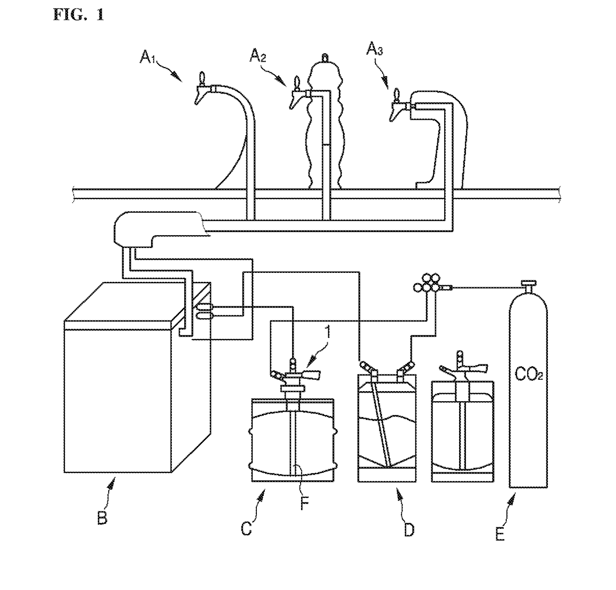
[0046]FIG. 1 is a diagram of an illustrative example of a beverage dispensing apparatus related to the present disclosure.

[0047]Conventional beverage dispensing system such as that illustrated in FIG. 1 may include dispensing faucets A1, A2 and A3 for different types of beverages, such as beer and carbonated beverage.

[0048]The supply of beer, cold drinks and syrup to a cooler or a carbonated water blender B may be carried out as follows.

[0049]Referring to FIG. 1, a conventional beverage dispensing apparatus includes a beer container C, one or more syrup containers D, which are shown as connected to a container C.

[0050]In addition, the beer container C and the one or more syrup containers D are connected to a source of pressurized carbon dioxide, that is, a cylindrical container or cylinder E.

[0051]At this time, the carbon dioxide is introduced in the beer container C and the syrup container D above their liquid surfaces.

[0052]The liquid is then pressurized so that it flows out throu...


PUM


Abstract

The present disclosure relates to a cleaning module-integrated beverage dispensing head, capable of selectively providing a cleaning function in addition to a conventional beverage dispensing function. A cleaning module-integrated beverage dispensing head includes a gas distributor (200) outputting a gas flowed in, and a pulse generator (100) receiving a supply of the gas supplied via a hose (300). The gas distributor (200) includes a first gas outlet (220) discharging the gas to the pulse generator (100), a second gas outlet (230) discharging the gas to a container (C) for storing liquid, an internal structure (200a) that is rotatable, and an external structure (200b) that is coupled to the internal structure (200a), to control rotation of the internal structure (200a). Whether or not to supply the gas to the pulse generator (100) through the first gas outlet (220) is determined according to whether or not the internal structure (200a) rotates.

Description

TECHNICAL FIELD[0001]The present disclosure relates to a cleaning module-integrated beverage dispensing head. More particularly, the present disclosure relates to an integrated beverage dispensing head capable of selectively providing a cleaning function in addition to a conventional beverage dispensing function.BACKGROUND[0002]Liquid supply pipes widely used in industrial equipment such as pipeline of a ship, piping of waste water sludge treatment facility, internal piping of construction plant equipment, beverage supply pipe in food and beverage equipment for the likes of beer, etc. are subject to the characteristics of internal liquid and environmental factors of the installation site, resulting in the inner walls being deposited with accumulation of foreign substances such as scales and bacteria, etc.[0003]Specifically, when various liquid foods and beverages flow along the conduit for a long time, corrosion occurs on the inner surface of the conduit. Corrosion results when meta...

Claims


Application Information

Patent Timeline
IPC IPC(8): B67D1/07B08B9/032B67D1/08
CPCB67D1/07B08B9/0326B67D1/08B08B9/032B08B9/0325
Inventor PARK, JONG-HA
Owner INTELLECTUAL DISCOVERY CO LTD
Why Eureka
Try Eureka