Abrasive and boring method using the same

Inactive Publication Date: 2005-11-01
MITSUBISHI MATERIALS CORP +1
View PDF9 Cites 3 Cited by
  • Summary
  • Abstract
  • Description
  • Claims
  • Application Information

AI Technical Summary

Benefits of technology

[0031]In this case, due to the particles of anhydrous silica, the fluidity of the abrasive becomes high, and the abrasive can be sufficiently supplied to the diamond segments at the distal end of the core bit. In addition, the diamond segments can further be cooled by efficiently supplying a hydrous resin and a sublimate in the abrasive to the diamond segments. Thereby, the boring of a deep hole can be carried out by the dry method in which the heat generation by the boring of the core bit is decreased, and while maintaining the boring speed without a reduction, the boring of a deep hole can be carried out using a dry method.
[0032]The boring method according to the present invention comprise

Problems solved by technology

However, in the case that the working material is hard, because the chips are reduced to fine particles, not only is realizing the dressing function of the diamond segments impossible, but the chips adhere to the binder material, the diamond abrasive grains are surrounded, and a ceramic-like state is formed having a surface that is dense and smooth.
This is because in the case of boring a deep hole by the dry method, even if the cooling fluid such as compressed air can be delivered along with the abrasive to and the distal end of the core bit, it is blocked in the narrow gap between the inner circumferential surface of the core bit and the inner circumferential wall of the cut groove that is being cut, and thus sufficient compressed air and abrasives cannot be supplied up to the distal end of the diamond segments.
In particular, in the case of boring a deep hole by the dry method, there is the problem that the abrasives become obstructed before they arrive at the distal end of the core bit, and as a result, the diamond segments are not sufficiently dressed.
Between diamond abrasive grains of the diamond segments or the regions that extend towards the upper axial direction from the diamond segments, the part indicated by the slanted line in FIG. 5 (shown i

Method used


Image

  • Abrasive and boring method using the same
  • Abrasive and boring method using the same
  • Abrasive and boring method using the same

Examples


Embodiment Construction

[0038]Below, the abrasive and the boring method using the same will be explained with reference to the figures.

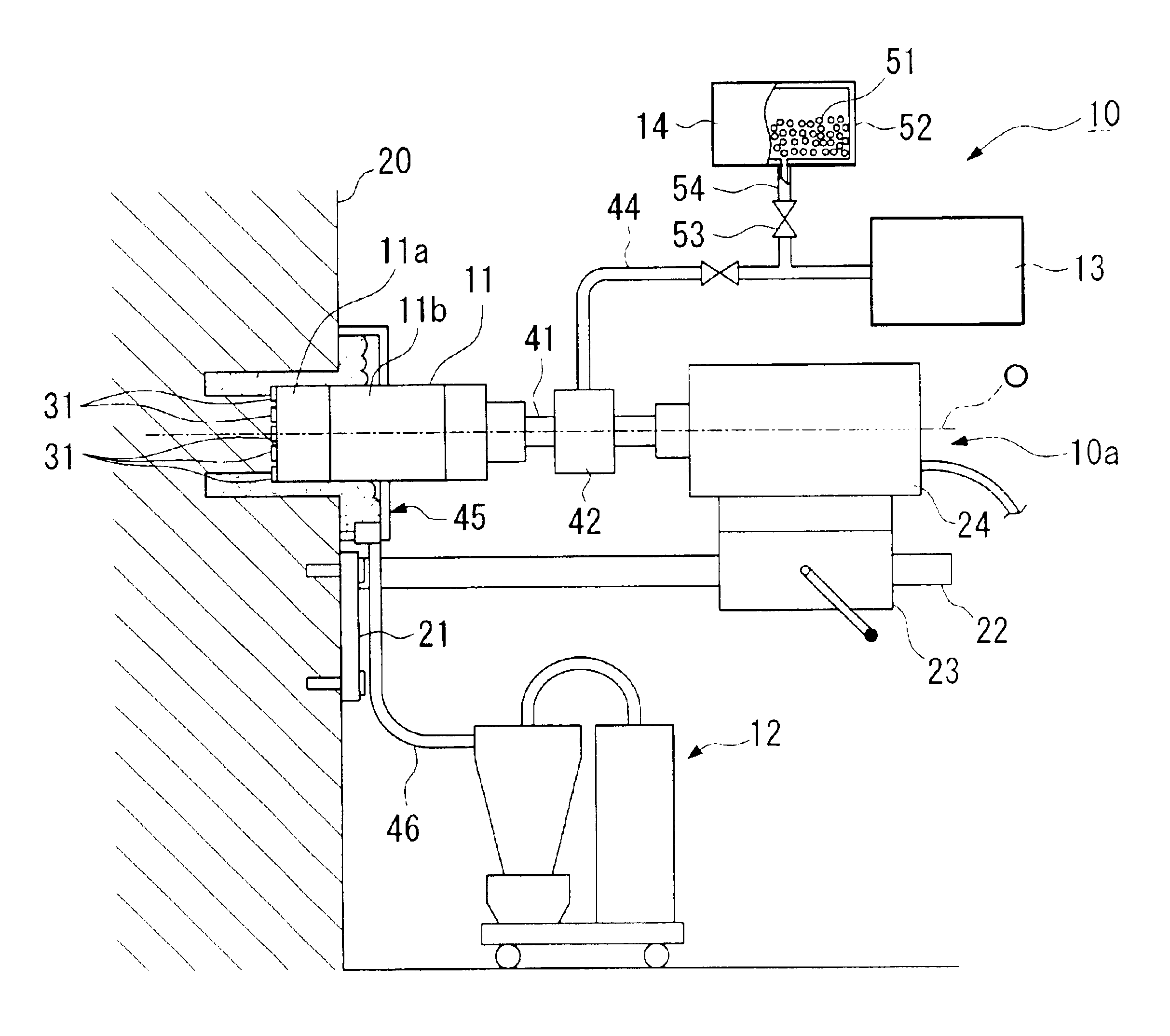
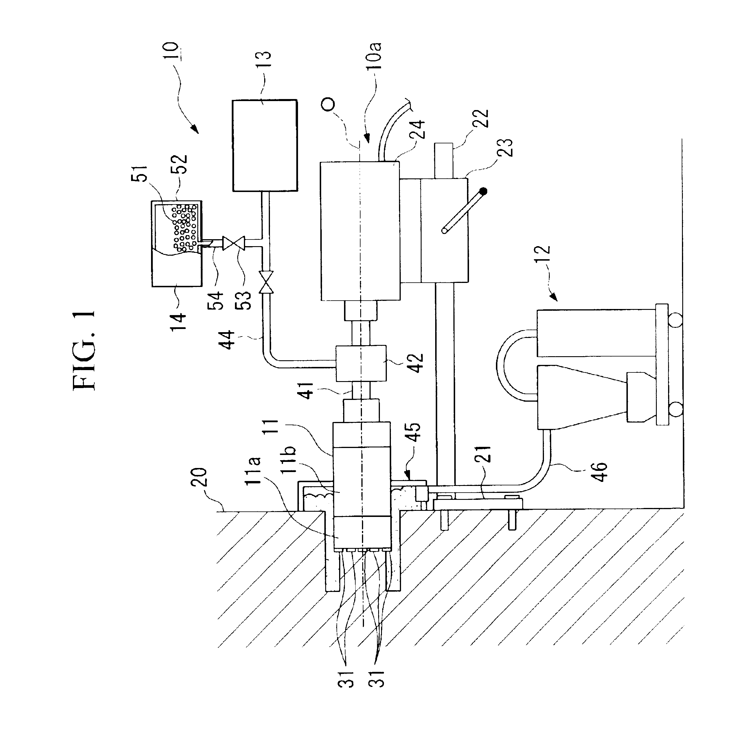
[0039]FIG. 1 is a structural drawing showing an example of a boring apparatus that uses the abrasive of the present invention.

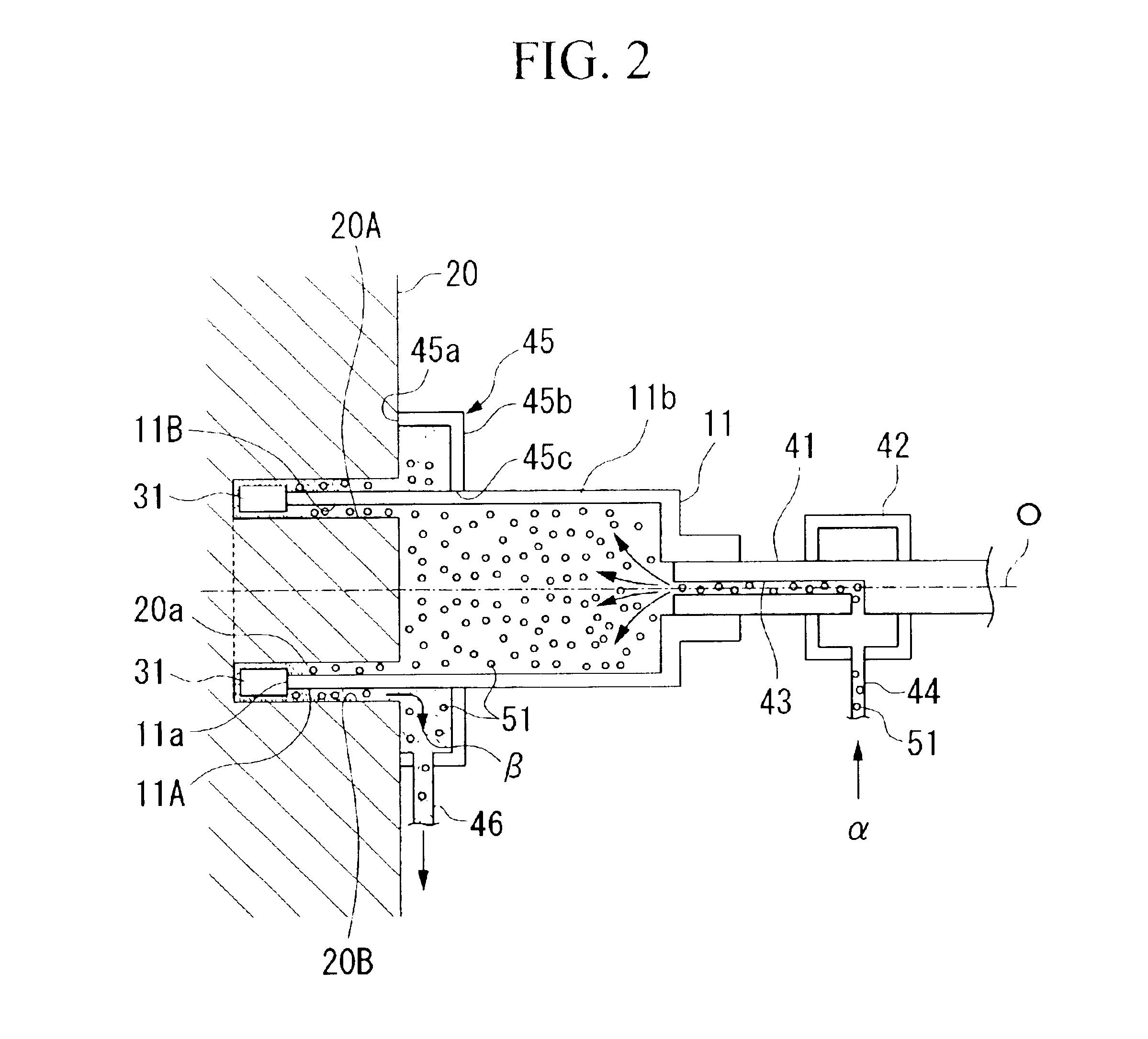
[0040]FIG. 2 is a cross-sectional drawing of the essential components showing the vicinity of the cylindrical core bit the boring apparatus 10 shown in FIG. 1.

[0041]In the figures, the boring apparatus 10 comprises an apparatus body 10a having a core bit 11, a dust collecting apparatus 12, for example, a cyclone-type dust collecting apparatus, that collects the chips, an air supplying apparatus 13 such as air compressor that supplies air to the boring member, and an abrasive supplying apparatus 14 that supplies the abrasive 51 that cools the boring member.

[0042]The abrasive supplying apparatus 14 comprises an abrasive tank 52 that accommodates the abrasive 51 and an abrasive supplying pipe 54 that communicates with the supply pipe 44 via a valve 53. ...


PUM

PropertyMeasurementUnit
Particle diameteraaaaaaaaaa
Massaaaaaaaaaa

Abstract

The present invention relates to an abrasive that decreases the heat generation by a core bit due to boring and allows the boring of a deep hole while maintaining the boring speed even when a deep hole is cut using a dry method. This abrasive contains abrasive grains, particles of anhydrous silica having a particle diameter from 5 nm to 50 nm and silanol groups in the surface thereof, and hydrous resin which discharges water when the hydrous resin is pressed by a core bit or the temperature of the hydrous resin rises. The abrasive 51 is supplied between the distal end of a rotating core bit 11 and a working material 20.

Description

BACKGROUND OF THE INVENTION[0001]1. Field of the Invention[0002]The present invention relates to an abrasive which can be advantageously used for dressing diamond segments of a core bit when boring a working material such as asphalt or concrete by the core bit, and a boring method using the abrasive.[0003]2. Description of the Related Art[0004]Conventionally, for boring a working material such as asphalt, concrete, or the like, a boring method is known in which a circular groove is cut into the working material wherein a core bit, which has diamond segments comprising diamond abrasive grains or the like attached to the distal end opening of a cylindrical core, is pressed against the working material while being rotated by a drive source such as a motor.[0005]The diamond segments are formed by dispersing diamond abrasive grains or the like in a binder phase made by sintering a binder material such as a metal bond. To maintain an advantageous boring condition, the new diamond abrasive...

Claims


Application Information

Patent Timeline
IPC IPC(8): B24B53/00B28D1/04B24B53/013B28D1/02C09K3/14B24D3/04B28D1/14
CPCB24B53/013B28D1/025C09K3/1409B28D1/041Y10T408/03B24D3/04
Inventor MAZAKI, SHIGERUKAWAHARA, TSUYOSHI
Owner MITSUBISHI MATERIALS CORP
Why Eureka
Try Eureka