Electric energy generating element

Inactive Publication Date: 2006-06-13
SONY CORP
View PDF9 Cites 0 Cited by
  • Summary
  • Abstract
  • Description
  • Claims
  • Application Information

AI Technical Summary

Benefits of technology

[0009]It is an object of the present invention to provide an electrical energy generating device for generating the electrical energy which enables atmospheri

Problems solved by technology

On the other hand, the earth is imperiled by a serious risk of environmental destruction.
Moreover, the resources of fossil fuel tend to be depleted such that difficulties are feared to be met as to a stable supply of fossil fuel over a long term.
Moreover, when

Method used


Image

  • Electric energy generating element
  • Electric energy generating element
  • Electric energy generating element

Examples


Embodiment Construction

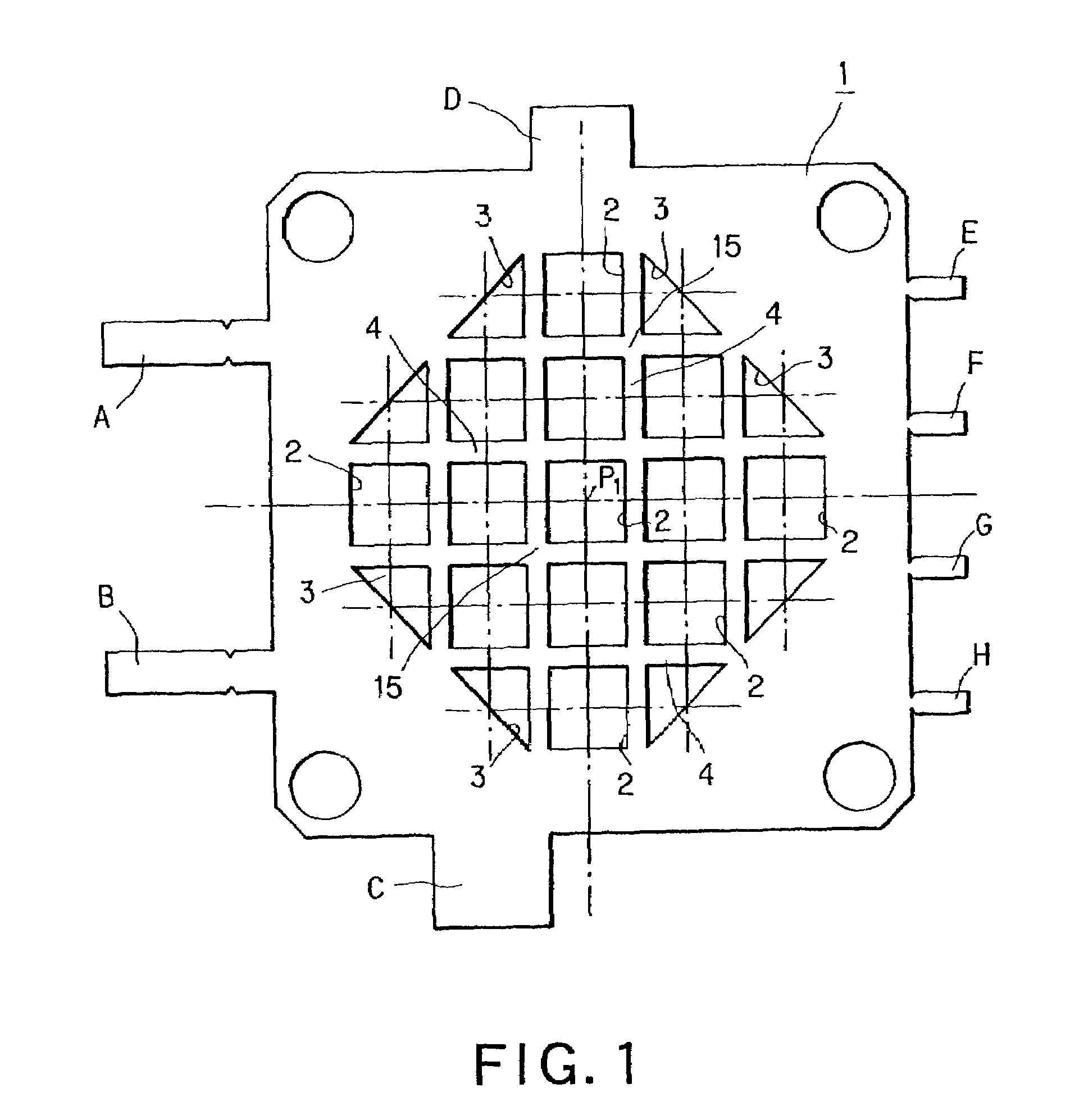
[0060]An electrical energy generating device according to the present invention includes a first hydrogen electrode plate 1 configured as shown in FIG. 1. This first hydrogen electrode plate 1 is formed by a substantially square-shaped plate member formed of a stainless steel. The thickness of the plate member forming the hydrogen electrode plate 1 is set to 0.01 mm to 1.0 mm.

[0061]Referring to FIG. 1, the hydrogen electrode plate 1 is formed by a lattice 4 having a regular array of 13 square-shaped apertures 2 and eight triangular apertures 3. The eight triangular apertures 3 are arranged on the periphery, whereas, of the 13 square-shaped apertures 2, the central aperture 2 is formed in coincidence with the center point of the first hydrogen electrode plate 1.

[0062]In FIG. 1, A to H are pins for connection across the electrodes, and are formed each to a rectangular shape.

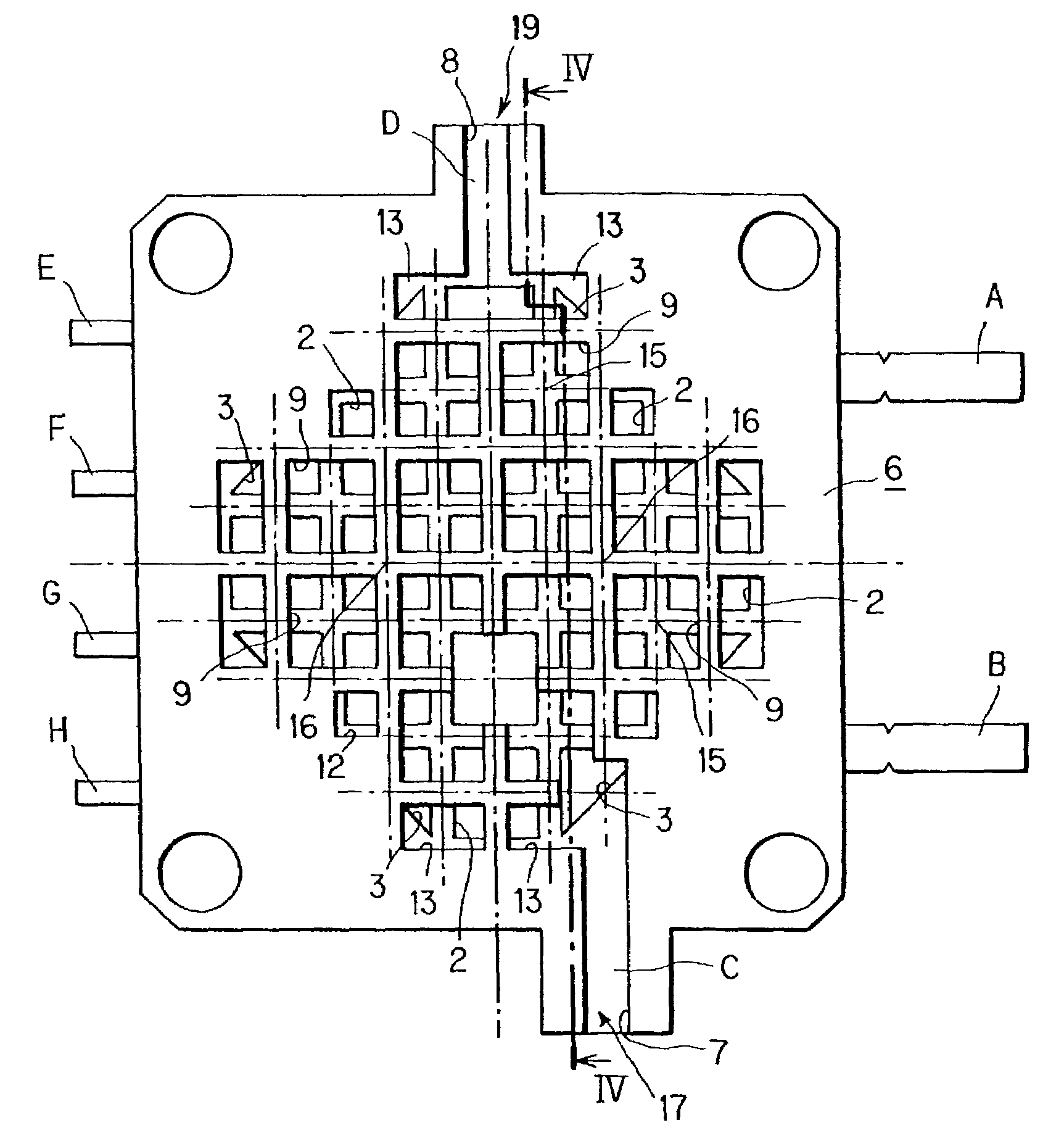
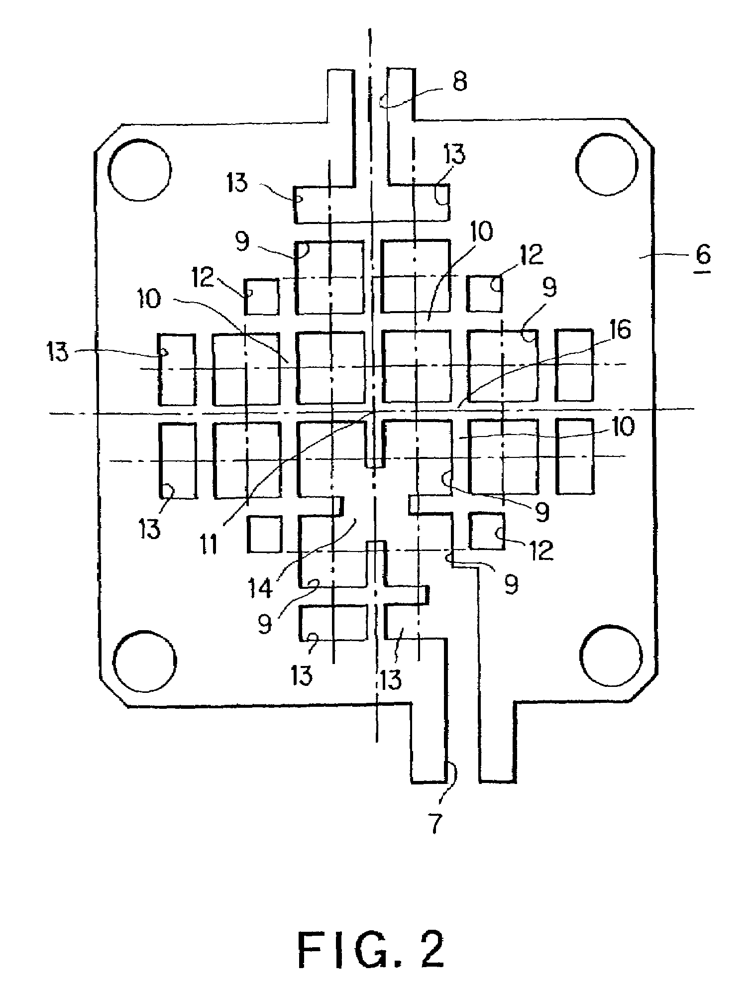
[0063]A hydrogen gas flow path plate 6 of the first unit electrical energy generating device constituting the el...


PUM

PropertyMeasurementUnit
Permeabilityaaaaaaaaaa

Abstract

An electrical energy generating device which is able to supply oxygen in atmospheric air efficiently to an oxygen electrode and to vaporize water yielded off efficiently, and which has superior waterproof characteristic. The device includes a number of cells each having a hydrogen electrode plate, a proton conductor film and an oxygen electrode plate, and a sheet cover 5 which is air-permeable and waterproofed and which shrouds each cell.

Description

BACKGROUND OF THE INVENTION[0001]The present invention relates to a device for generating electrical energy. More particularly, it relates to a device for generating electrical energy which enables atmospheric air to be supplied efficiently to an oxygen electrode, which efficiently vaporizes off the water yielded and which has superior waterproof characteristics.[0002]Until now, fossil fuels, such as gasoline or light oil, have been used extensively not only as an energy source for automobiles, but also as an energy source for power generation. Through the use of these fossil fuels, mankind could enjoy such benefits as drastically improved quality of life or industrial development. On the other hand, the earth is imperiled by a serious risk of environmental destruction. Moreover, the resources of fossil fuel tend to be depleted such that difficulties are feared to be met as to a stable supply of fossil fuel over a long term.[0003]Recently, hydrogen is attracting attention as an ener...

Claims


Application Information

Patent Timeline
IPC IPC(8): H01M2/00H01M2/02H01M2/14H01M8/02H01M8/04H01M8/24
CPCH01M8/0239H01M8/0247H01M8/241H01M8/04119Y02E60/50H01M8/04156H01M8/2457
Inventor MIYAKOSHI, MITSUAKIMIYAZAWA, HIROSHIWATANABE, TOMIKAZUYAMAURA, KIYOSHIMARUYAMA, RYUICHIROTAKIZAWA, SHUICHI
Owner SONY CORP
Why Eureka
Try Eureka