Manufacturing of decorative workpieces by inkjet

a technology of inkjet printing and workpieces, applied in the field of manufacturing decorative workpieces, can solve the problems of increasing waste, not a solution, and increasing waste of decorative workpieces, and achieve the effects of quick response on specific situations, ability to react quickly, and manufacturing can continue fas

Active Publication Date: 2016-12-01
AGFA NV +1
View PDF2 Cites 25 Cited by
  • Summary
  • Abstract
  • Description
  • Claims
  • Application Information

AI Technical Summary

Benefits of technology

[0018]An advantage of a nesting method is the ability to quickly respond on specific situations during the manufacturing of decorative workpieces. For example, the current technology of digital print devices has fundamental weaknesses compared to conventional print devices such as rotogravure or offset, especially when it comes to high-speed digital printing of decorative patterns on a decoration layer. When a digital print device fails to print in a specific zone at the moment the manufacturing of the decorative workpieces have to be stopped to solve the failing of the digital print device, this has an impact on the production and manufacturing timings. The nesting method may arrange the set of decorative patterns digital printed on the decoration layer in the quality zone of a digital print device and/or in the quality zone of a cutting plotter so that the manufacturing can continue fast without the need of directly solving the failing. A specific failing of a digital print device is the malfunction of a nozzle in an inkjet print head of an inkjet print device. In a single pass inkjet print device this causes a non-printed line in the print zone of the sin...

Problems solved by technology

An increase in waste of decorative workpieces has been observed on performing the digital printing of decorative patterns at the facilities of the laminate manufacturer.
This increase of waste is observed not only in the more frequent short run productions, but especially when sizes of digital printed decorative patterns are different or when the shapes of digital printed decorative patterns are...

Method used


Image

  • Manufacturing of decorative workpieces by inkjet
  • Manufacturing of decorative workpieces by inkjet
  • Manufacturing of decorative workpieces by inkjet

Examples


Embodiment Construction

Content Extension Area

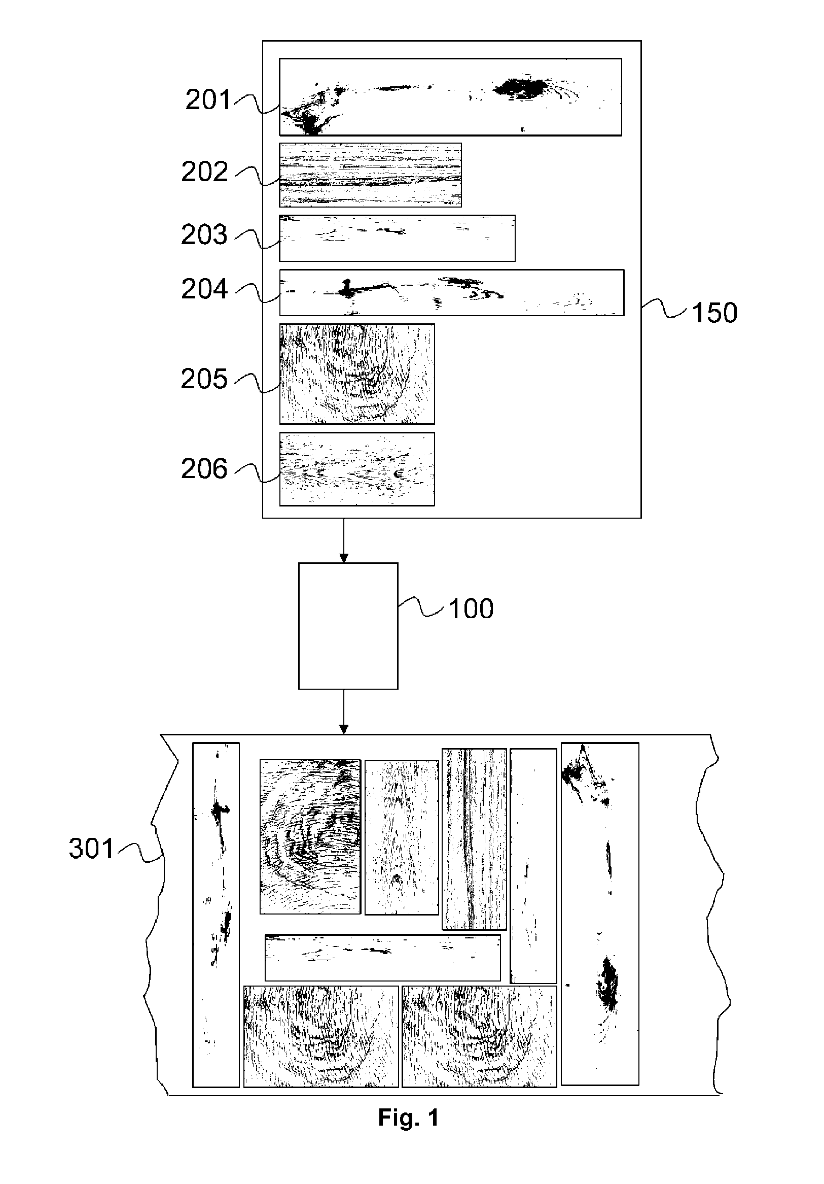
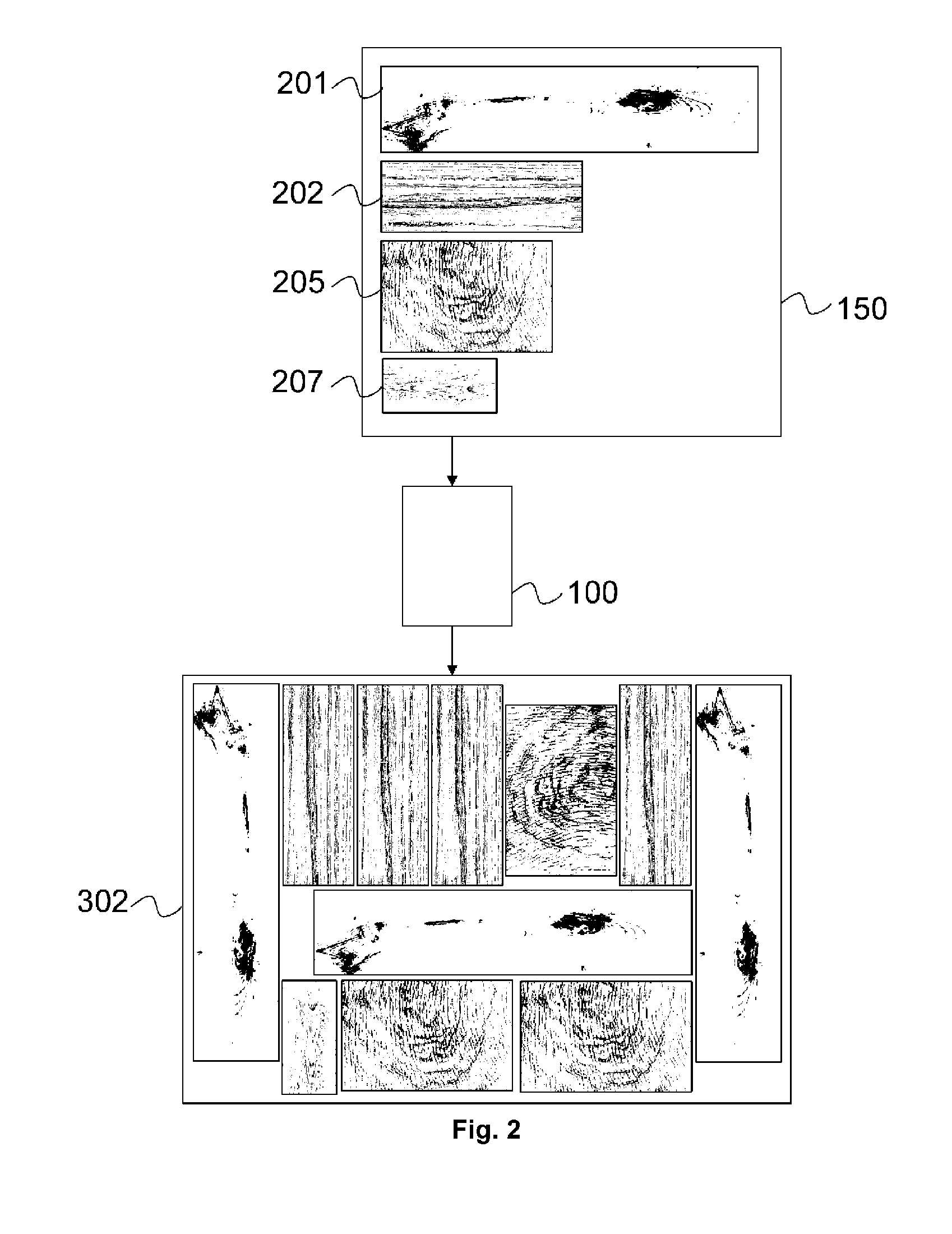
[0043]To compensate inaccuracies in the printing process and / or finishing process and / or provide extension to a decorative pattern to mount a decorative workpiece, in, for example three-dimensional object content, extension areas have to be designed in a decorative pattern before finishing the decorative workpiece.

[0044]Examples of content extension areas are:[0045]glue area: an area that will be glued afterwards while mounting the decorative workpieces to a finished product;[0046]connect area: an area to provide means that will be attached while mounting the decorative workpieces to a finished product. An example of such means is a tongue-and-groove profile on a decorative workpiece;[0047]folding area: an area that will be folded and / or attached while mounting the print to a finished product. For example flaps that are needed to fold a flexible decorative workpiece, such as a vinyl tile to a box or around stair;[0048]bleed area: Several finishing processes are...


PUM


Abstract

A method for manufacturing decorative workpieces includes the step of nesting a set of decorative patterns digitally printed on a decoration layer to reduce the waste of decoration layer. To perform a corresponding relief for the nested decorative patterns on a nested decorative workpiece, the relief provided by a digital relief apparatus is in a correct match with the nested decorative workpiece. If the printing zone of the digital printer has a failure zone, the nesting method prevents arranging of the decorative patterns in this failure zone.

Description

CROSS-REFERENCE TO RELATED APPLICATIONS[0001]This application is a 371 National Stage Application of PCT / EP2015 / 052165, filed Feb. 3, 2015. This application claims the benefit of European Application No. 14154309.0, filed Feb. 7, 2014, which is incorporated by reference herein in its entirety.BACKGROUND OF THE INVENTION[0002]1. Field of the Invention[0003]The present invention relates to methods for manufacturing decorative workpieces such as decorative panels.[0004]2. Description of the Related Art[0005]Gravure, offset and flexography are being increasingly replaced for different applications by industrial inkjet printing systems, which have now proven their flexibility in use, such as variable data printing making short production runs and personalized products possible, and their enhanced reliability, allowing incorporation into production lines.[0006]Inkjet technology, as digital printing technology has also caught the attention of manufacturers of decorative surfaces, such as l...

Claims


Application Information

Patent Timeline
IPC IPC(8): B41J3/407B41J2/01
CPCB41J2/01B41J3/4073B44C5/04G06F3/1219G06F3/1251G06F3/1208G06F3/1262H04N1/00H04N1/3872
Inventor CLOOTS, TOMMEERSSEMAN, LAURENTVAN GARSSE, JORIS
Owner AGFA NV
Why Eureka
Try Eureka