Control device for vehicle

a control device and vehicle technology, applied in hybrid vehicles, electrical control, machines/engines, etc., can solve the problems of fuel pipe dripping, residual pressure holding valve closing, opening/closing noise that may sound unpleasant to passengers, etc., and achieve the effect of reducing the noise generated by the residual pressure holding valv

Active Publication Date: 2016-12-01
TOYOTA JIDOSHA KK
View PDF10 Cites 2 Cited by
  • Summary
  • Abstract
  • Description
  • Claims
  • Application Information

AI Technical Summary

Benefits of technology

[0008]An object of the present disclosure is to provide a control device for a vehicle in which noise generated by the residual pressure holding valve has been reduced.

Problems solved by technology

This causes the pressure in the fuel pipe to decrease below the valve opening pressure of the residual pressure holding valve, which causes the residual pressure holding valve to close again.
The repeated opening and closing of the residual pressure holding valve (with chattering being generated) is undesired in that this opening / closing noise may sound unpleasant to a passenger.

Method used


Image

  • Control device for vehicle
  • Control device for vehicle
  • Control device for vehicle

Examples


first embodiment

[0073]Thus, in the first embodiment, at the time of a request to reduce the target fuel pressure, the request is not permitted when the engine output is low, and is permitted when the engine output is high.

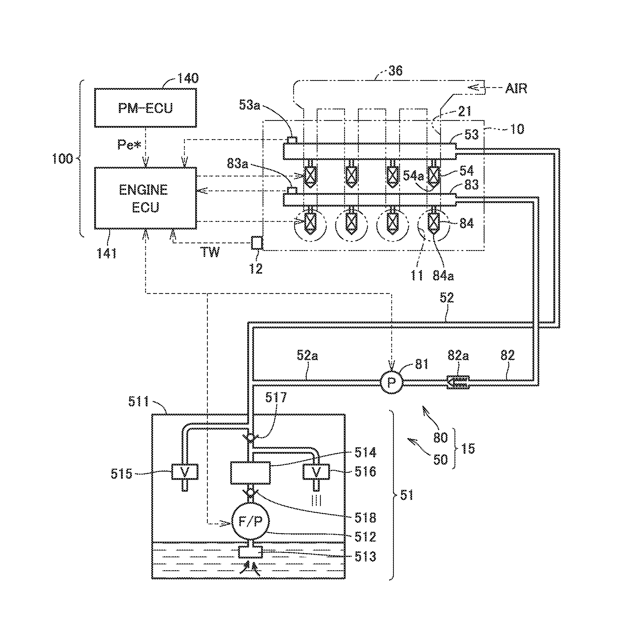
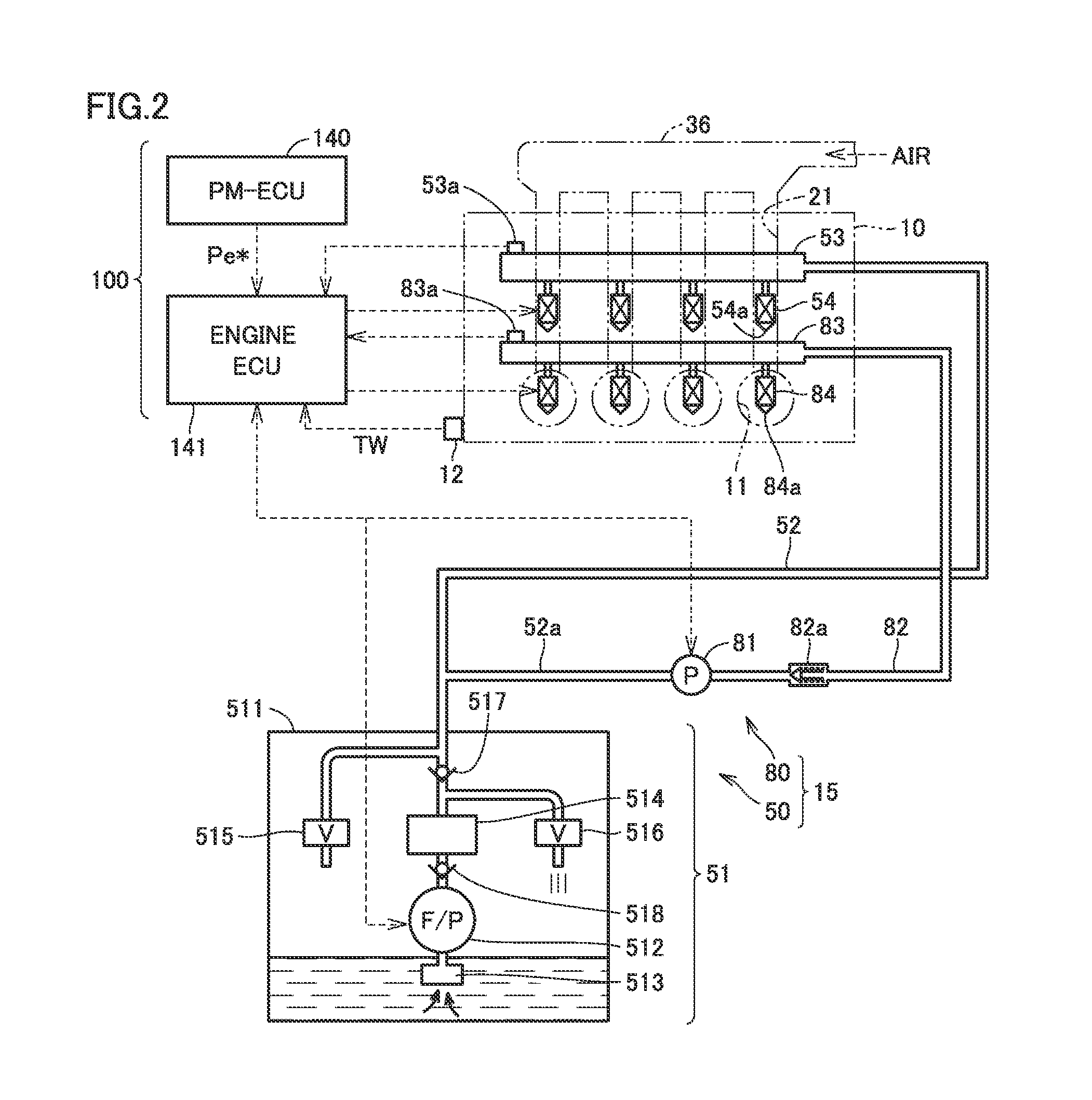
[0074]Referring to FIG. 2 and a right-half section of FIG. 3, when engine output Pe is relatively high, rotation speed Np of feed pump 512 is also set high. In this state, if the target fuel pressure is reduced, rotation speed Np of feed pump 512 decreases, but is still higher than that shown by the left-half waveform. Then, because engine output Pe is high, the amount of injected fuel is large, so that even though the fuel is discharged through residual pressure holding valve 516, check valve 517 is opened to supply the fuel to the fuel pipe. In this state, actual fuel pressure Pf in low-pressure delivery pipe 53 and low-pressure fuel pipe 52 is equal to or lower than fuel pressure Pm in fuel filter module 514. Hence, fuel pressure Pm in the module can still be kept higher than t...

second embodiment

[0084]In the first embodiment, the target fuel pressure is reduced by waiting until the engine load exceeds the prescribed power. Thus, there is a possibility that a high target fuel pressure may be continued. Leaving the target fuel pressure unnecessarily high is undesired in that a loss may be produced in feed pump 512, leading to reduced fuel efficiency.

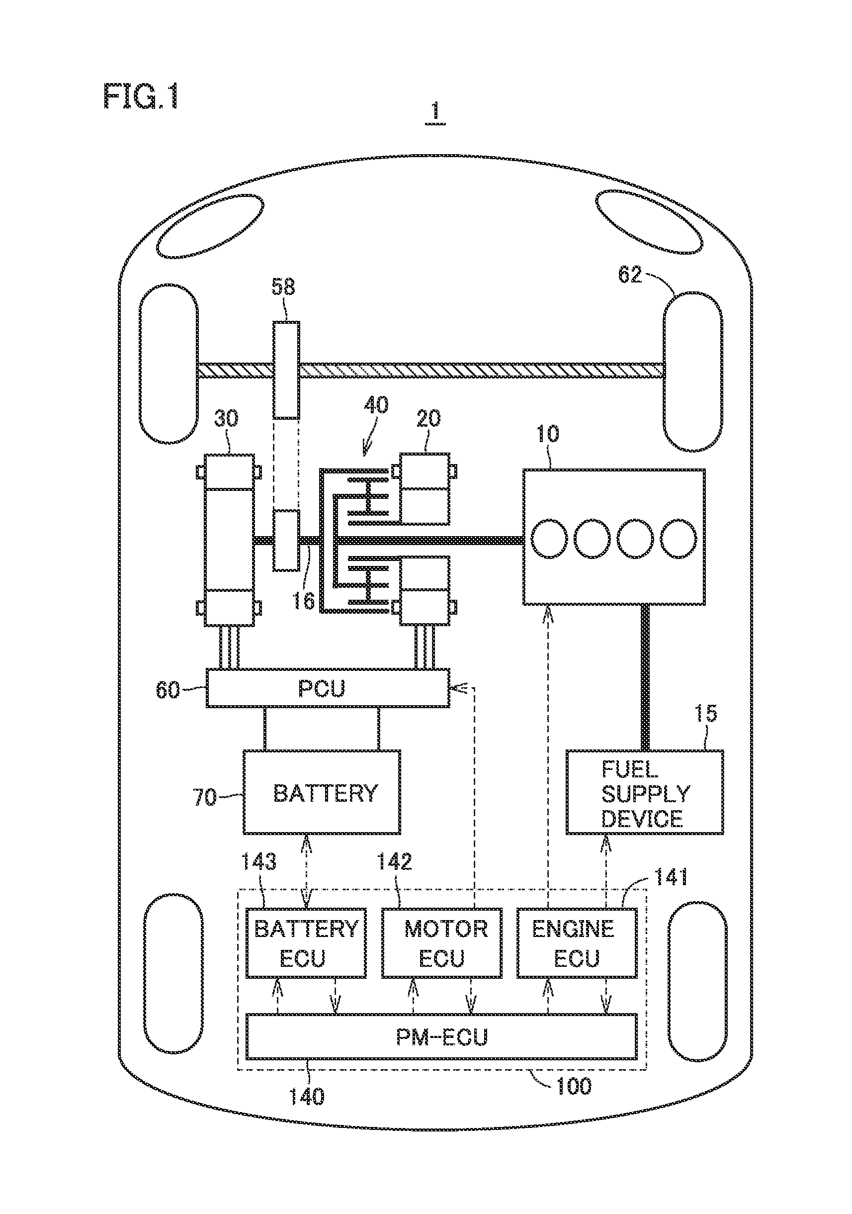
[0085]In the second embodiment, therefore, timing is created for allowing the target fuel pressure to decrease by increasing the engine load, while preventing a reduction in fuel efficiency. In the case of the hybrid vehicle as shown in FIG. 1, charging power (Pchg) for charging the battery is also reflected in engine power, separately from running power requested by the user with the accelerator pedal. In the second embodiment, therefore, at the time of a request to reduce the target fuel pressure, when the engine load does not exceed the prescribed power, the charging power is increased for charging the battery while increasing ...

third embodiment

[0094]In the second embodiment, when the engine load is low, the engine load is increased before target fuel pressure Pt is reduced. It is, however, not always necessary to increase the engine load prior to reducing target fuel pressure Pt. The third embodiment describes an example in which target fuel pressure Pt is reduced before the engine load is increased.

[0095]In the third embodiment, when the load of engine 10 has become smaller than a prescribed value (DkW) by reducing the target pressure of the fuel to be supplied to feed pump 512 below the target pressure in the previous cycle, control device 100 causes the load of engine 10 to increase above the prescribed value (DkW). Note that the prescribed value (DkW) corresponds to the “third prescribed value” in the claims.

[0096]FIG. 7 is an operation waveform diagram for use in illustrating operation in the third embodiment. Referring to FIG. 7, from times t10 to t11, target fuel pressure Pt remains about 640 kPa, and actual fuel p...


PUM


Abstract

A vehicle includes a residual pressure holding valve provided downstream a feed pump of a fuel to hold a pressure in a fuel pipe leading to the port injection valve. Residual pressure holding valve is opened to return the fuel in the fuel pipe to the fuel tank when the pressure in the fuel pipe exceeds a valve opening pressure, and closed when the pressure in the fuel pipe is lower than the valve opening pressure. At the time of a request to reduce a target pressure of the fuel to be supplied to the electric feed pump, a control device refrains from causing the target pressure to decrease when a load of the engine is smaller than a prescribed value, and causes the target pressure to decrease when the load of the engine is greater than the prescribed value.

Description

CROSS-REFERENCE TO RELATED APPLICATIONS[0001]This nonprovisional application claims priority to Japanese Patent Application No. 2015-107400 filed on May 27, 2015 with the Japan Patent Office, the entire contents of which are hereby incorporated by reference.BACKGROUNDTechnical Field[0002]The present disclosure relates to a control device for a vehicle, and particularly to a control device for a vehicle equipped with an internal combustion engine including a fuel injection valve.Description of the Background Art[0003]Japanese Patent Laying-Open No. 2012-097640 discloses a fuel supply device including a residual pressure holding valve that is disposed downstream a fuel feed pump to hold the pressure in a pipe for supplying a fuel to a fuel injection valve of an engine at a prescribed pressure during stoppage of the feed pump.[0004]When the operation of the engine is stopped and the fuel feed pump is stopped, the residual pressure holding valve is closed to prevent the pressure in the ...

Claims


Application Information

Patent Timeline
Patent Type & Authority Applications(United States)
IPC IPC(8): F02M51/04F02M37/00B60L50/16
CPCF02M37/0047F02M51/04F02M37/0023F02M37/0052F02M37/08F02D41/3082F02D41/3094F02M69/046F02M2200/09F02D41/3854F02D2200/0602F02D2250/31F02D2041/3881F02M63/029F02M37/46B60K6/445Y02T10/62B60W10/06
Inventor MITSUOKA, RYUHEI
Owner TOYOTA JIDOSHA KK
Why Eureka
Try Eureka