Pitch system locking arrangement

a technology of pitch system and locking arrangement, which is applied in the direction of mechanical control devices, process and machine control, instruments, etc., can solve the problems of parts that need to be controlled and maintained, several parts that need to be mounted, and emergency situations in wind turbines. achieve the effect of improving the arrangement as a locking mechanism

Active Publication Date: 2016-12-01
SIEMENS GAMESA RENEWABLE ENERGY AS
View PDF9 Cites 11 Cited by
  • Summary
  • Abstract
  • Description
  • Claims
  • Application Information

AI Technical Summary

Benefits of technology

[0015]The aim of embodiments of the invention is therefore

Problems solved by technology

An emergency situation in a wind turbine might occur due to the loss of the grid connection of a technical problem like the loss of a viable technical system.
This shows the d

Method used


Image

  • Pitch system locking arrangement
  • Pitch system locking arrangement
  • Pitch system locking arrangement

Examples


Embodiment Construction

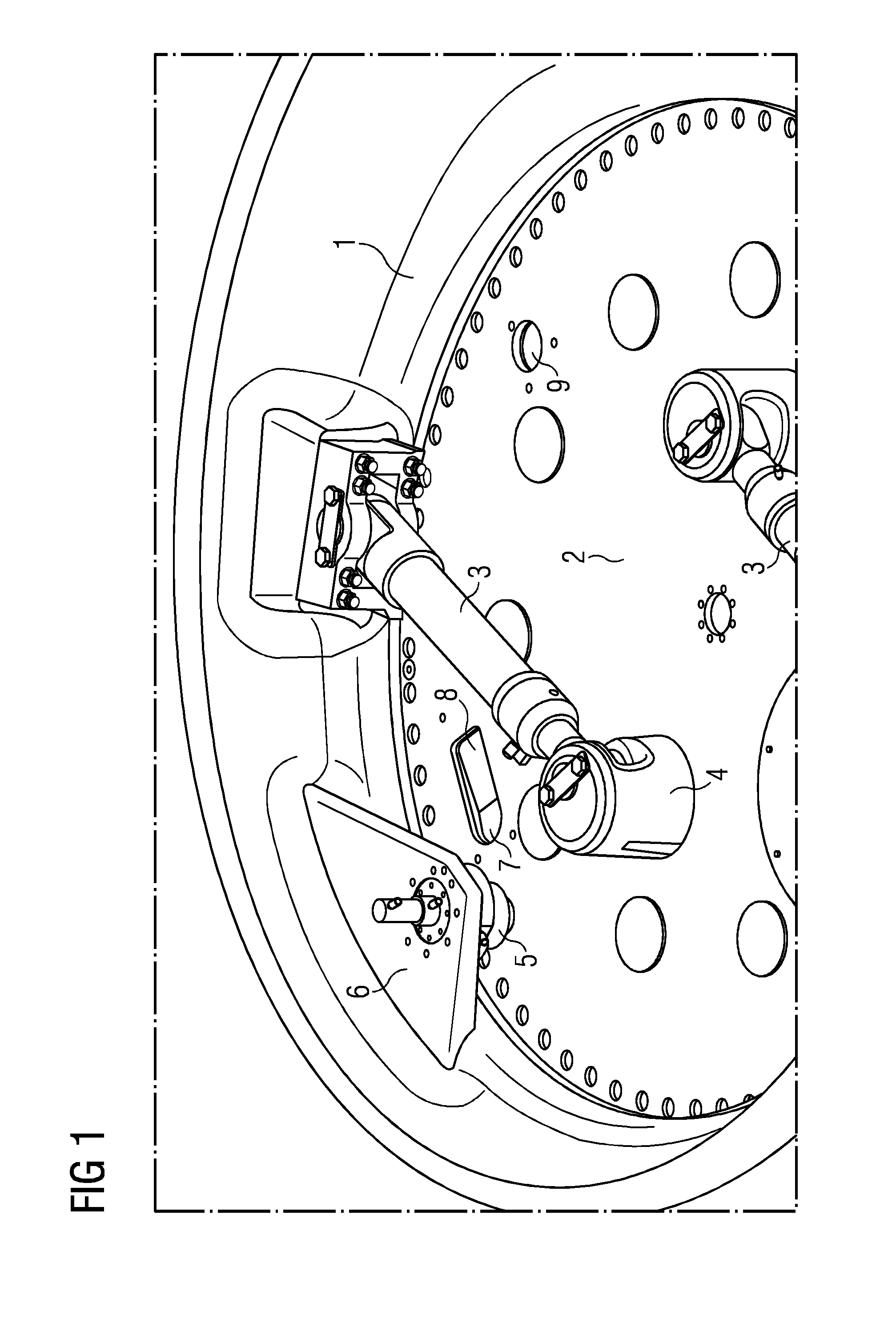
[0063]FIG. 1 shows a pitch drive of a rotor blade.

[0064]FIG. 1 shows a pitch drive system for a rotor blade. The pitch drive system comprises a hydraulic cylinder 3 that is at its one end connected to the hub 1 and at its other end connected to the reinforcement plate 2 by a connection point 4.

[0065]The reinforcement plate 2 is connected to the rotor blade and is rotatable together with the rotor blade with respect to the hub 1. When the hydraulic cylinder 3 expands, it implies a force into the connection point 4 between the hydraulic cylinder 3 and the reinforcement plate 2, and rotates the reinforcement plate 2 in respect to the hub 1.

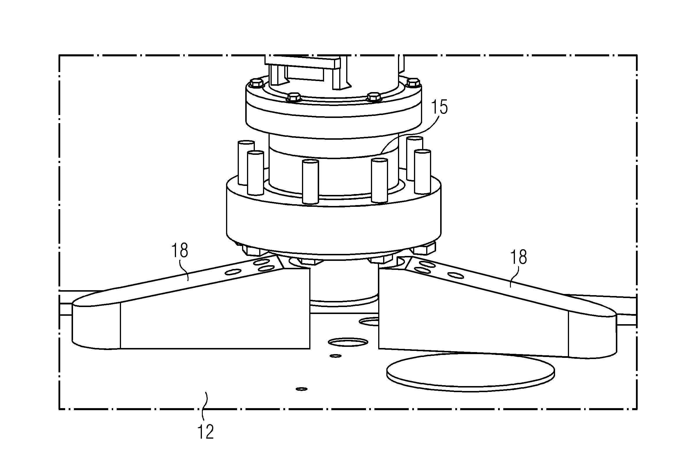
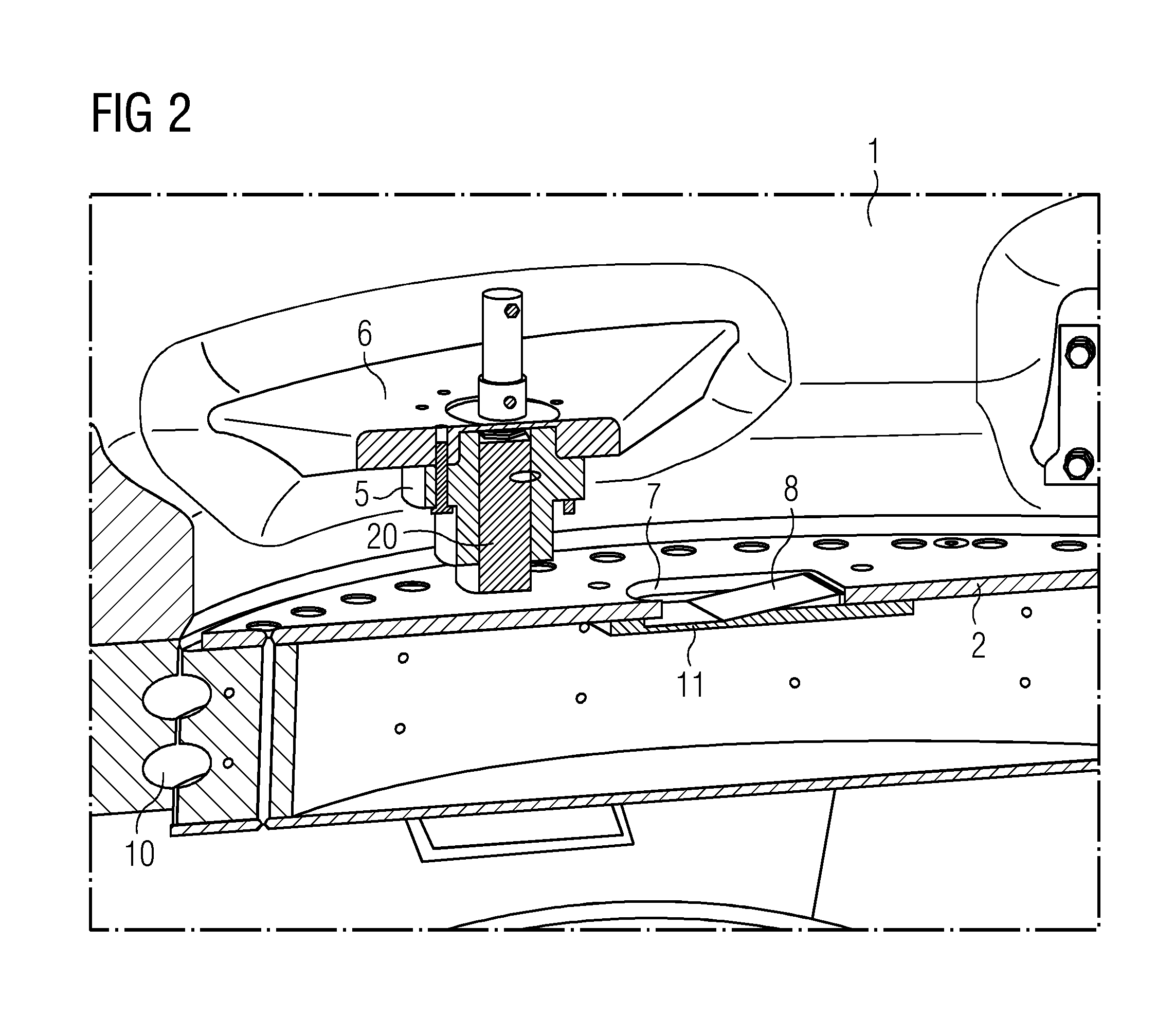
[0066]To arrest the pitch of the rotor blade in a certain position in the case of an emergency, a locking system for the pitch has to be provided.

[0067]The locking system for the pitch comprises a pitch lock 5 that is connected to a support 6 to the hub 1 of the wind turbine. The pitch lock 5 comprises a drive and a locking pawl.

[0068]To secure a pos...


PUM


Abstract

A pitch system locking arrangement is provided. A rotor of a wind turbine is disclosed with a pitch system locking arrangement to lock the position of a wind turbine rotor blade. A rotor comprises a rotor hub and a rotor blade, whereby the rotor blade is connected to the hub via a bearing, to be rotatable in respect to the hub in a pitch movement. The rotor blade comprises a root section, and the root section comprises a plate, that at least partially covers the cross section of the rotor blade. A certain predetermined rotational position of the rotor blade in respect to the hub 1 is a locked position. The hub includes a locking pawl. The plate comprises an opening, and the locking pawl is at least partially located in the opening of the plate, when the rotor blade is in the locked position.

Description

CROSS-REFERENCE TO RELATED APPLICATIONS[0001]This application claims priority to European application No. EP 15169430.4 having a filing date of May 27, 2015 the entire contents of which are hereby incorporated by reference.FIELD OF TECHNOLOGY[0002]The following relates to a pitch system locking arrangement.BACKGROUND[0003]A wind turbine comprises a rotor that is equipped with rotor blades. The rotor converts the energy of the moving air into rotational energy of the rotor that is then transformed into electrical energy in the generator of the wind turbine.[0004]The rotor blades are connected to the hub of the rotor in a way that they can be rotated around their longitudinal axis. Thus the rotor blades can perform a pitch movement relative to the hub.[0005]The pitch movement is needed to control the rotational speed of the rotor and the performance of the wind turbine.[0006]When the wind turbine is not in operation, the rotor blades are arrested in a stop position.[0007]In an emergen...

Claims


Application Information

Patent Timeline
IPC IPC(8): F03D7/02F03D80/70F03D1/06
CPCF03D7/0224F03D1/0658F05B2260/406F05B2260/30F03D80/70F03D7/00F03D7/0244Y02E10/72F16B1/04F16D71/04G05G5/18
Inventor EBBESEN, HENNINGLAURSEN, CHRISTIAN
Owner SIEMENS GAMESA RENEWABLE ENERGY AS
Why Eureka
Try Eureka