
Integrated APU Generator Constant Speed Drive

a constant speed drive, apu-generator technology, applied in the direction of engine starters, machines/engines, gearing, etc., can solve the problems of existing apu-generator systems encountering operational challenges

Inactive Publication Date: 2016-12-01
HAMILTON SUNDSTRAND CORP
View PDF3 Cites 18 Cited by
  • Summary
  • Abstract
  • Description
  • Claims
  • Application Information

AI Technical Summary

Benefits of technology

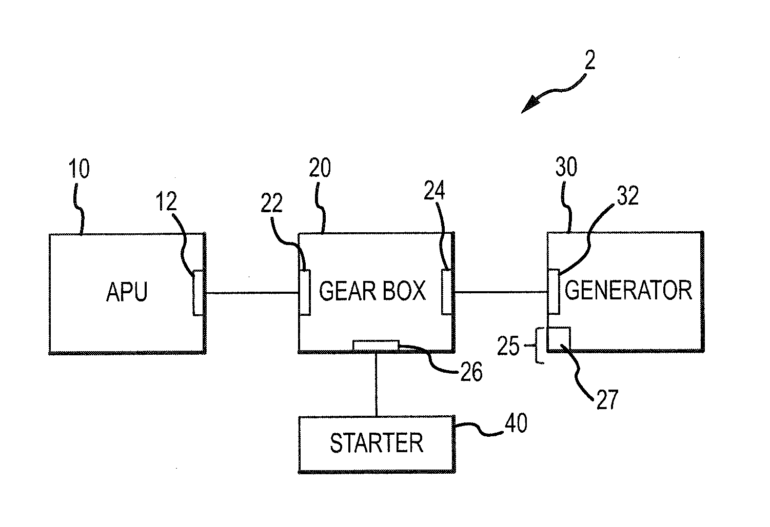
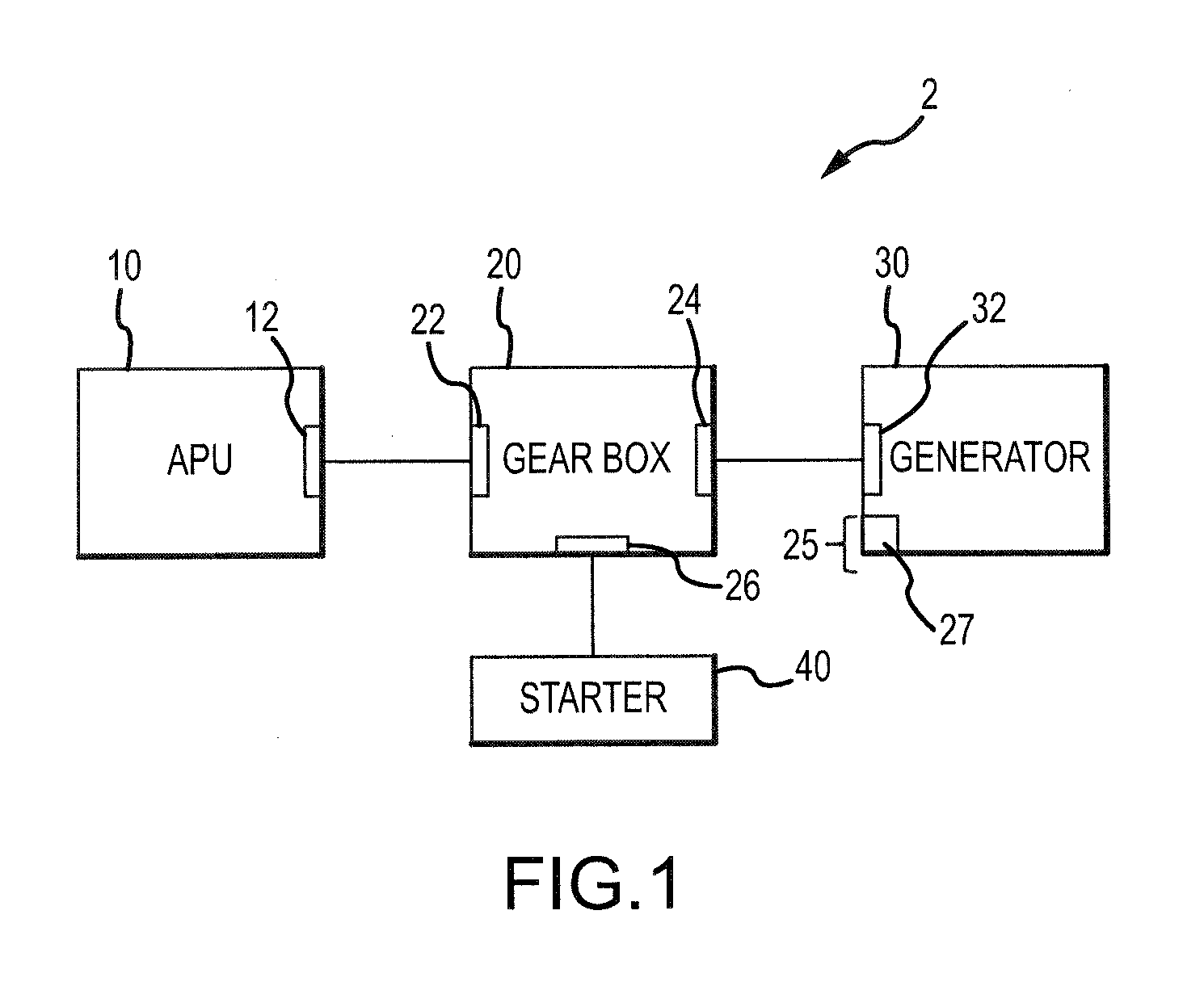
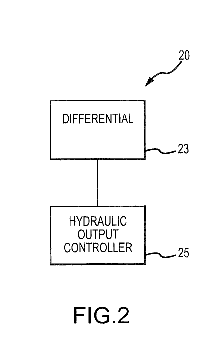
The present invention is about an integrated system that includes an auxiliary power unit and a constant speed gearbox. The auxiliary power unit has a variable frequency rotational output, and the constant speed gearbox has a constant speed output. The gearbox is connected to the variable frequency output and helps transfer energy from the output to the constant speed output. The invention also includes a method of controlling the speed of the constant speed gearbox. This method involves rotating the variable frequency rotational output at a non-constant angular velocity, driving a differential, and rotating the constant speed gearbox output. The speed of the constant speed gearbox output is sensed using a speed sensor, and a servomotor operates a swash plate to control the speed of the hydraulic output controller control shaft. This helps regulate the speed of the constant speed gearbox output to a constant angular velocity.

Problems solved by technology

However, existing APU-generator systems encounter operational challenges.
However, maintaining a high throttle setting during times of reduced electrical load or increased APU efficiency expends large amounts of fuel.

Method used


Image

  • Integrated APU Generator Constant Speed Drive
  • Integrated APU Generator Constant Speed Drive
  • Integrated APU Generator Constant Speed Drive

Examples


Embodiment Construction

[0011]The following description is of various exemplary embodiments only, and is not intended to limit the scope, applicability or configuration of the present disclosure in any way. Rather, the following description is intended to provide a convenient illustration for implementing various embodiments including the best mode. As will become apparent, various changes may be made in the function and arrangement of the elements described in these embodiments without departing from the scope of the appended claims. Furthermore, any reference to singular includes plural embodiments, and any reference to more than one component or step may include a singular embodiment or step. Surface shading lines may be used throughout the figures to denote different parts but not necessarily to denote the same or different materials.

[0012]For the sake of brevity, conventional techniques for manufacturing and construction may not be described in detail herein. Furthermore, the connecting lines shown in...


PUM


Abstract

An integrated APU-generator constants speed drive system having various features is disclosed. The system may have a gearbox having a differential with a constant speed gearbox output and a hydraulic output controller control shaft. The system may have a hydraulic output speed controller that adjusts the angular velocity of the hydraulic output controller control shaft of the differential. In response, the differential may adjust the angular velocity of the constant speed gearbox output. In this manner, the angular velocity of the constant speed gearbox output may be maintained at a substantially constant angular velocity. A generator may be driven by the constant speed gearbox output. By maintaining the constant speed gearbox output at a substantially constant angular velocity, an alternating current generated by the generator may be maintained at a substantially constant frequency.

Description

FIELD[0001]The present disclosure relates to the field of electrical power generation. More particularly, the present disclosure relates to an auxiliary power unit generator constant speed drive system in which an auxiliary power unit operating at varying speeds drives a generator at a constant speed.BACKGROUND[0002]Airplanes have utilized various auxiliary power units (“APUs”) in combination with generators to provide electrical power. However, existing APU-generator systems encounter operational challenges. For example, the frequency of the alternating current produced by the generator depends on the rotational speed of the generator. Because the APU provides the rotational impetus driving the generator, the APU is also operated at a constant rotational speed to maintain a constant frequency alternating current. The APU rotational speed is controlled by the APU throttle setting (which varies with altitude). Thus, it remains preferable to keep the APU at a specific, generally high,...

Claims


Application Information

Patent Timeline
Patent Type & Authority Applications(United States)
IPC IPC(8): F16H61/47F02C7/36F02N11/04F16H47/04
CPCF16H61/47F16H47/04F05D2260/406F02N11/04F05D2260/40311F02C7/36F02C7/275F02C7/32F05D2220/50Y02T50/60
Inventor LEMMERS, JR., GLENN C.WELCH, TIMOTHY R.
Owner HAMILTON SUNDSTRAND CORP
Learn More