ESD protection device and common mode choke coil with built-in ESD protection device

Active Publication Date: 2016-12-01
MURATA MFG CO LTD
View PDF2 Cites 15 Cited by
  • Summary
  • Abstract
  • Description
  • Claims
  • Application Information

AI Technical Summary

Benefits of technology

The present invention provides a small ESD protection device that reduces or prevents discharge between multiple electrodes, even if multiple devices are placed in a shared hollow portion. It also includes a common mode choke coil with this ESD protection device.

Problems solved by technology

In the case where a multilayer body having a structure in which ESD protection devices are separately formed in each hollow portion is miniaturized, there arises a problem such that a plurality of hollow portions are disposed nearby each other and consequently the hollow portions are connected to each other.
Because of this, in the structure where the hollow portions are individually provided for each ESD protection device, a certain amount of occupation space needs to be secured, which makes it difficult to realize the miniaturization.
However, in the case where the above structure is used, when static electricity enters a transmission line, in addition to the occurrence of discharge between the discharge electrode and the ground electrode, abnormal discharge among the plurality of discharge electrodes is likely to occur because the plurality of discharge electrodes are arranged adjacent to each other in the shared hollow portion.
In the case where the discharge among the discharge electrodes (hereinafter, referred to as “abnormal discharge”) occurs, the static electricity having entered one transmission line moves to another transmission line, which raises a risk of breakdown of an electronic circuit such as an IC or the like that is connected to a subsequent stage of a common mode choke coil.

Method used


Image

  • ESD protection device and common mode choke coil with built-in ESD protection device
  • ESD protection device and common mode choke coil with built-in ESD protection device
  • ESD protection device and common mode choke coil with built-in ESD protection device

Examples


first preferred embodiment

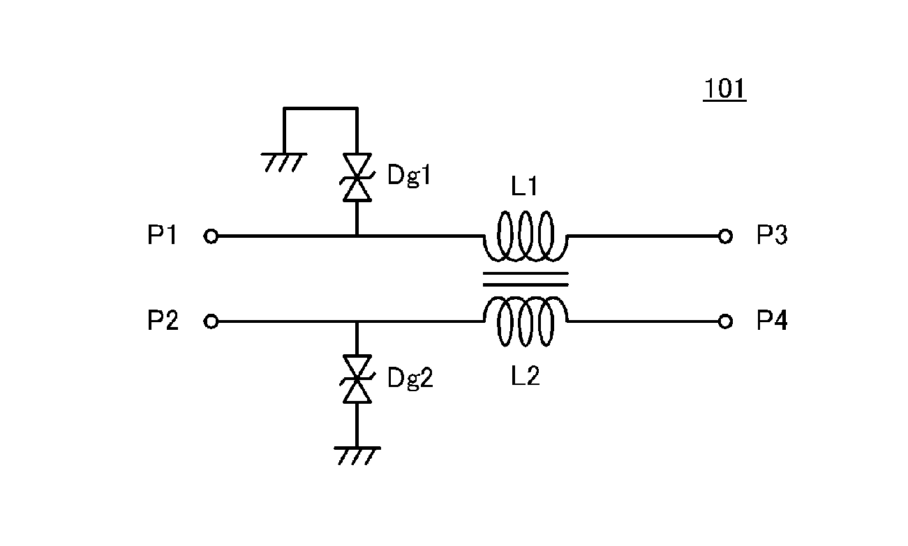
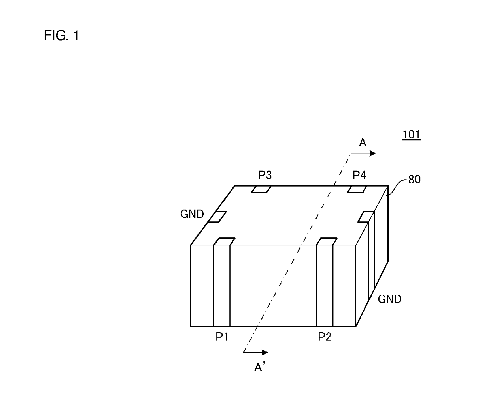
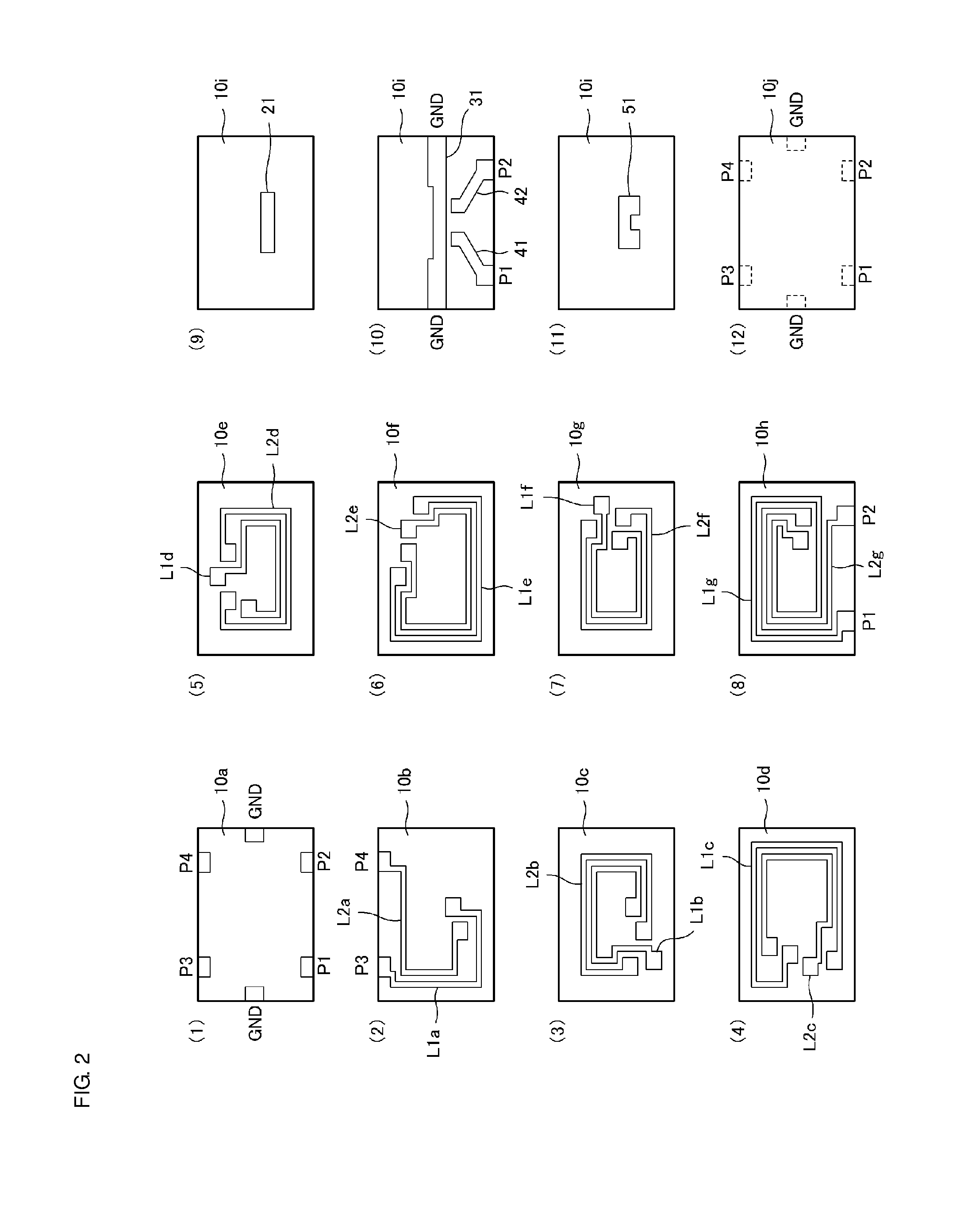
[0039]A common mode choke coil with a built-in ESD (electro-static discharge) protection device according to a first preferred embodiment of the present invention will be described with reference to the drawings. FIG. 1 is a perspective view of exterior appearance of a common mode choke coil with a built-in ESD protection device 101 according to the first preferred embodiment. FIG. 2 includes exploded plan views illustrating an electrode pattern and the like of each base material layer of the common mode choke coil with a built-in ESD protection device 101 according to the first preferred embodiment. FIG. 3 is a cross-sectional view taken along an A-A′ line in FIG. 1. In FIG. 3, in order to facilitate understanding of the drawing and operation principle, the structure of the common mode choke coil with a built-in ESD protection device 101 is illustrated in a simplified manner. Note that in FIG. 3, thicknesses of the respective portions are illustrated in an exaggerated manner. The s...

second preferred embodiment

[0084]With reference to the drawings, a common mode choke coil with a built-in ESD protection device according to a second preferred embodiment of the present invention will be described. FIG. 7 includes exploded plan views illustrating an electrode pattern and the like of each base material layer of a common mode choke coil with a built-in ESD protection device 102 according to the second preferred embodiment. FIG. 8 is a cross-sectional view of the common mode choke coil with a built-in ESD protection device 102 according to the second preferred embodiment. FIG. 9 is a circuit diagram of the common mode choke coil with a built-in ESD protection device 102 according to the second preferred embodiment.

[0085]As shown in FIG. 9, the common mode choke coil with a built-in ESD protection device 102 according to the second preferred embodiment differs from the common mode choke coil with a built-in ESD protection device 101 according to the first preferred embodiment in that an ESD prote...

third preferred embodiment

[0097]A common mode choke coil with a built-in ESD protection device according to a third preferred embodiment of the present invention will be described with reference to the drawings. FIG. 10 is a perspective view of exterior appearance of a common mode choke coil with a built-in ESD protection device 103 according to the third preferred embodiment. FIG. 11 includes exploded plan views illustrating an electrode pattern and the like of each base material layer of the common mode choke coil with a built-in ESD protection device 103 according to the third preferred embodiment. FIG. 12 is a circuit diagram of the common mode choke coil with a built-in ESD protection device 103 according to the third preferred embodiment.

[0098]The common mode choke coil with a built-in ESD protection device 103 according to the third preferred embodiment differs from the common mode choke coil with a built-in ESD protection device 101 according to the first preferred embodiment in that an input-output ...


PUM


Abstract

An ESD protection device includes a multilayer body including base material layers, a hollow portion inside the multilayer body, a ground electrode exposed at the hollow portion, first and second discharge electrodes exposed at the shared hollow portion and opposing the common ground electrode, and an auxiliary discharge electrode including conductive particles dispersed in the base material layer and extending along an inner surface of the hollow portion. At least the auxiliary discharge electrode in an adjacent region between the first discharge electrode and the second discharge electrode is divided into a portion on the first discharge electrode side and a portion on the second discharge electrode side by a non-formation section where the auxiliary discharge electrode is not provided in the hollow portion.

Description

CROSS REFERENCE TO RELATED APPLICATIONS[0001]This application claims the benefit of priority to Japanese Patent Application 2014-234127 filed Nov. 19, 2014 and is a Continuation Application of PCT / JP2015 / 078716 filed on Oct. 9, 2015. The entire contents of each application are hereby incorporated herein by reference.BACKGROUND OF THE INVENTION[0002]1. Field of the Invention[0003]The present invention relates to an ESD protection device, and a common mode choke coil with a built-in ESD protection device including an integral structure including an ESD protection device and a common mode choke coil in a multilayer body.[0004]2. Description of the Related Art[0005]ESD (electro-static discharge) is a phenomenon in which discharge occurs when an electrically-charged conductive substance (a human body, connector, or the like) makes contact with or comes close enough to another conductive substance (an electronic apparatus or the like). ESD protection devices are configured to release ESD ...

Claims


Application Information

Patent Timeline
IPC IPC(8): H01F27/40H05F3/04H01F27/29
CPCH01F27/402H05F3/04H01F27/292H01F17/0013H01F2017/0093H01T4/08H01T4/10H01T4/12H05K1/0259H05K1/026H01C7/12H01F17/00H01F27/00
Inventor SHIGEMATSU, SATOSHI
Owner MURATA MFG CO LTD
Why Eureka
Try Eureka