Antenna structures for wireless communications

a wireless communication and antenna technology, applied in the field of wireless communication systems, can solve the problems of limiting the range of coverage at 60 ghz, high path loss, and high penetration loss, and achieve the effect of facilitating reception and/or transmission

Active Publication Date: 2016-12-01
QUALCOMM INC
View PDF71 Cites 76 Cited by
  • Summary
  • Abstract
  • Description
  • Claims
  • Application Information

AI Technical Summary

Benefits of technology

[0009]The described features generally relate to one or more improved systems, methods, and / or apparatuses for wireless communication using the mmW spectrum. In particular, an antenna structure may be designed to integrate with an external housing of a wireless communication device. For example, the external housing may include a cavity that facilitates reception and / or transmission of radio frequency communication signals by an antenna element of the antenna structure. Such an antenna structure may be designed to be relatively compact to deal with the limited real estate available on modern wireless communication devices (e.g., cellular telephones).

Problems solved by technology

However, there are several challenges associated with this spectrum, such as reflection and scattering losses, high penetration loss and high path loss, which limit the range of coverage at 60 GHz.
Conventional antenna structures designed for lower frequencies (e.g., 800 MHz, 900 MHz, 1800 MHz, 1900 MHz, 2100 MHz, etc.) may include a single omnidirectional antenna (sometimes two or three for diversity) and may be unsuitable for mmW spectrum applications.

Method used


Image

  • Antenna structures for wireless communications
  • Antenna structures for wireless communications
  • Antenna structures for wireless communications

Examples


Embodiment Construction

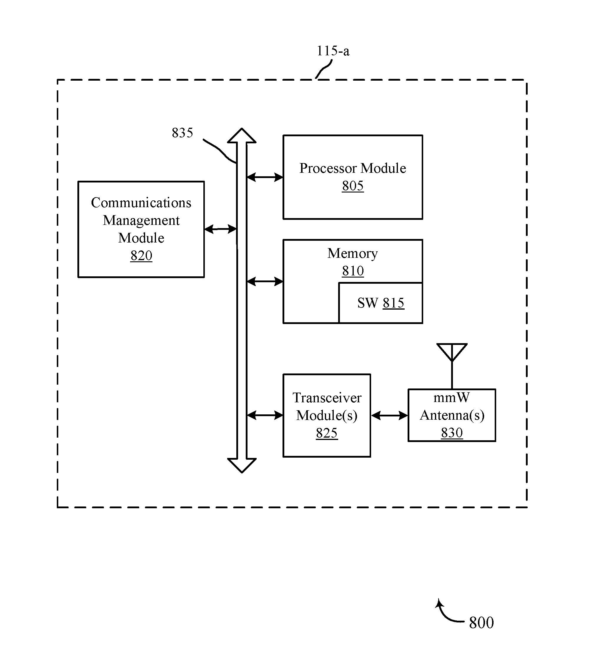
[0036]When a mmW antenna is included in a wireless communication device, the mmW antenna may be configured to receive and / or transmit communication signals through an external housing of the wireless communication device. The external housing conventionally may form a rear cover of the device with a display screen disposed on a front side of the device. Due to electromagnetic shielding by the display screen, reception / transmission of communication signals may be restricted to be through the rear cover. Further, electromagnetic shielding may prohibit a rear cover made of a metallic material from being disposed over the mmW antenna.

[0037]A plastics material may be used for the rear cover at least over the mmW antenna to allow reception / transmission of communication signals therethrough. However, the radiation of such communication signals may still be distorted by reflection and / or refraction caused by the rear cover over the mmW antenna.

[0038]Therefore, an antenna structure may be de...


PUM


Abstract

Methods, systems, and devices are described for wireless communication using the mmW spectrum. In particular, an antenna structure may be designed to integrate with an external housing of a wireless communication device. For example, the external housing may include a cavity that facilitates reception and/or transmission of radio frequency communication signals by an antenna element of the antenna structure. Such an antenna structure may be designed to be relatively compact to deal with the limited real estate available on modern wireless communication devices (e.g., cellular telephones).

Description

CROSS REFERENCES[0001]The present application for patent claims priority to U.S. Provisional Patent Application No. 62 / 166,496 by Ou, entitled “Antenna Structures For Wireless Communications,” filed May 26, 2015, assigned to the assignee hereof.BACKGROUND[0002]Field of the Disclosure[0003]The present disclosure, for example, relates to wireless communications systems, and more particularly to antenna structures for wireless communications.[0004]Description of Related Art[0005]Wireless communications systems are widely deployed to provide various types of communication content such as voice, video, packet data, messaging, broadcast, and so on. These systems may be multiple-access systems capable of supporting communication with multiple users by sharing the available system resources (e.g., time, frequency, and power). Examples of such multiple-access systems include code-division multiple access (CDMA) systems, time-division multiple access (TDMA) systems, frequency-division multipl...

Claims


Application Information

Patent Timeline
Patent Type & Authority Applications(United States)
IPC IPC(8): H01Q1/24H01Q1/42
CPCH01Q1/42H01Q1/241H01Q9/0407H01Q13/02H01Q19/00H01Q21/064H01Q21/065H01Q23/00H01L2223/6677H01L2924/15321H01L2224/16227H01Q1/2283H01Q1/243
Inventor OU, YU-CHIN
Owner QUALCOMM INC
Why Eureka
Try Eureka