Oscillatory wave motor

a technology of oscillatory wave and motor, which is applied in the direction of generator/motor, electrical apparatus, electric/electrostriction/magnetostriction machines, etc., can solve the problems of inability to achieve stable motor performance, and inability to significantly change flexibility. to achieve the effect of stable motor performan

Active Publication Date: 2016-12-01
CANON KK
View PDF1 Cites 4 Cited by
  • Summary
  • Abstract
  • Description
  • Claims
  • Application Information

AI Technical Summary

Benefits of technology

[0008]The invention is made to solve the above-mentioned problem and an object of the invention is to provide an oscillatory motor that is difficult to be influenced by the manufacturing variation and is stable in motor performance.
[0022]According to the invention, there can be provided an oscillatory wave motor that is less subject to variation upon manufacturing to provide stable motor performance.

Problems solved by technology

However, the oscillatory wave motor disclosed in Japanese Patent Application Laid-Open No. 2011-234608 is significantly influenced by variation during manufacturing of the elastic member so that there is possibility that stable motor performance may not be obtained.
Therefore, depending on dimensional variation of the connecting portion, there is possibility that the flexibility may be changed significantly and stable motor performance cannot be obtained.

Method used


Image

  • Oscillatory wave motor
  • Oscillatory wave motor
  • Oscillatory wave motor

Examples


embodiment

[0035]Basic embodiments to which the present invention is applied will be specifically described with reference to the accompanying drawings. In the drawings, the same components are denoted by the same reference numerals. It is needless to say that the following embodiments will be exemplary explained and the invention is not limited thereto.

[0036]Although an oscillatory wave motor of the embodiment is explained with an example of a linear driving type of motor that is unitized as a driving actuator for a lens mirror barrel of digital camera and so on, use is not limited thereto.

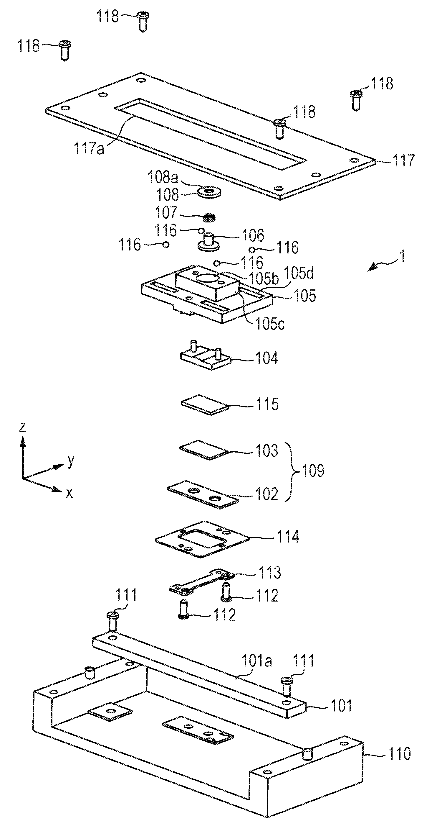
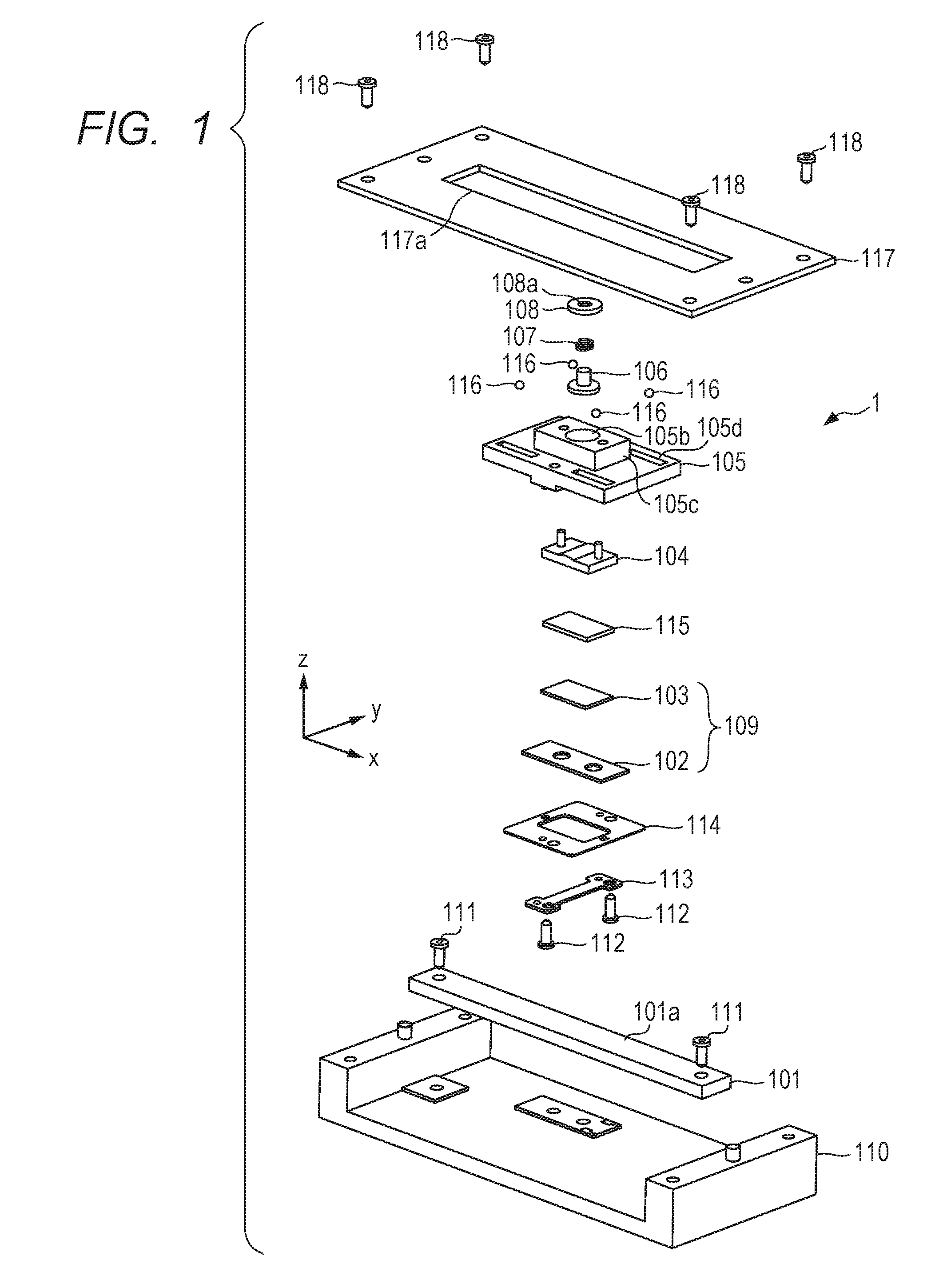
[0037]FIG. 1 is an exploded perspective view illustrating an oscillatory wave motor 1 according to an embodiment of the invention. It is noted that the same components are denoted by the same reference numerals in the drawings.

[0038]In the specification, a direction in which a vibrator 109 to be described is moved by elliptical vibration (elliptical motion) occurring to the vibrator 109 is defined as an X d...


PUM


Abstract

An oscillatory wave motor includes a piezoelectric element, an elastic member that includes a projecting portion, a friction member that moves relative to the elastic member and includes a contact surface in contact with the projecting portion, and pressing unit that brings the projecting portion into contact under pressure with the contact surface in a pressing direction that is a direction of a perpendicular line of the contact surface. The projecting portion includes a spherical portion formed in a center of the projecting portion, a contact portion formed on or near a center of the spherical portion, a flat portion formed around the spherical portion, and a corner portion formed around the flat portion. The spherical portion, the flat portion and the corner portion are configured to have a uniform thickness and to have flexibility in the pressing direction with the contact portion as a center.

Description

BACKGROUND OF THE INVENTION[0001]Field of the Invention[0002]The present invention relates to an oscillatory wave motor that drives a friction member by causing a vibrator that is pressed to generate elliptical movement.[0003]Description of the Related Art[0004]Oscillatory wave motors are configured in such a manner that a contact portion where a flexible member is fixed and a friction member are in a pressed contact state. When under the pressed contact state, a two-phase voltage is applied to the piezoelectric element and a two-phase vibration is generated, elliptical vibration is generated at the contact portion of the elastic member and the friction member is displaced relative to the elastic member. To follow the elliptical vibration stably, a predetermined amount of flexibility is needed between the contact portion and the friction member. Japanese Patent Application Laid-Open No. 2011-234608 discloses an oscillatory wave motor configured to include a thin connecting portion h...

Claims


Application Information

Patent Timeline
Patent Type & Authority Applications(United States)
IPC IPC(8): H02N2/02
CPCH02N2/026H02N2/0065
Inventor OIKAWA, MAKOTO
Owner CANON KK
Why Eureka
Try Eureka