Guide wheel, steering bogie, and vehicle

a technology of steering bogies and guides, which is applied in the direction of tyre parts, railway components, transportation and packaging, etc., can solve the problems of affecting the maintenance effect of the running wheel, so as to achieve the effect of improving the maintenance effect and easy determination of the wear situation

Active Publication Date: 2016-12-08
MITSUBISHI HEAVY IND ENG LTD
View PDF1 Cites 21 Cited by
  • Summary
  • Abstract
  • Description
  • Claims
  • Application Information

AI Technical Summary

Benefits of technology

[0039]In the guide wheel, the steering bogie, and the vehicle, the wear situation can be easily determined, and thus it is possible to improve maintainability.

Problems solved by technology

In a case where the guide width is narrower than a desired width, a gap between the guide wheel and the guide rail is increased, and thus there is a concern that smooth steering of the running wheel may not be performed.
Further, in a case where the guide width is wider than a desired width, there is a concern that it may lead to damage to the guide wheel or damage to the guide frame or the guide rail.

Method used


Image

  • Guide wheel, steering bogie, and vehicle
  • Guide wheel, steering bogie, and vehicle
  • Guide wheel, steering bogie, and vehicle

Examples


first embodiment

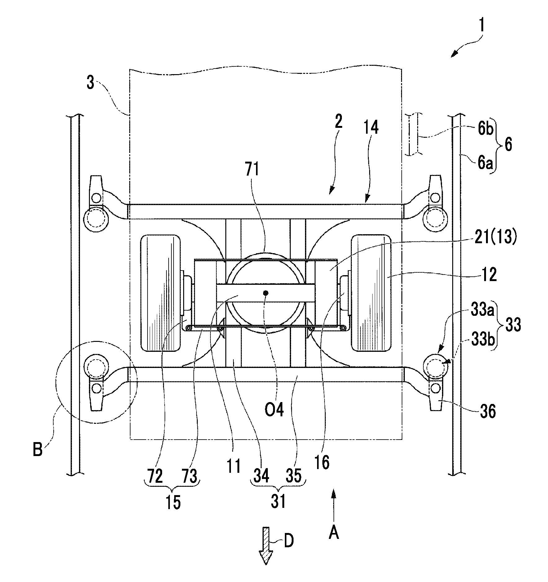
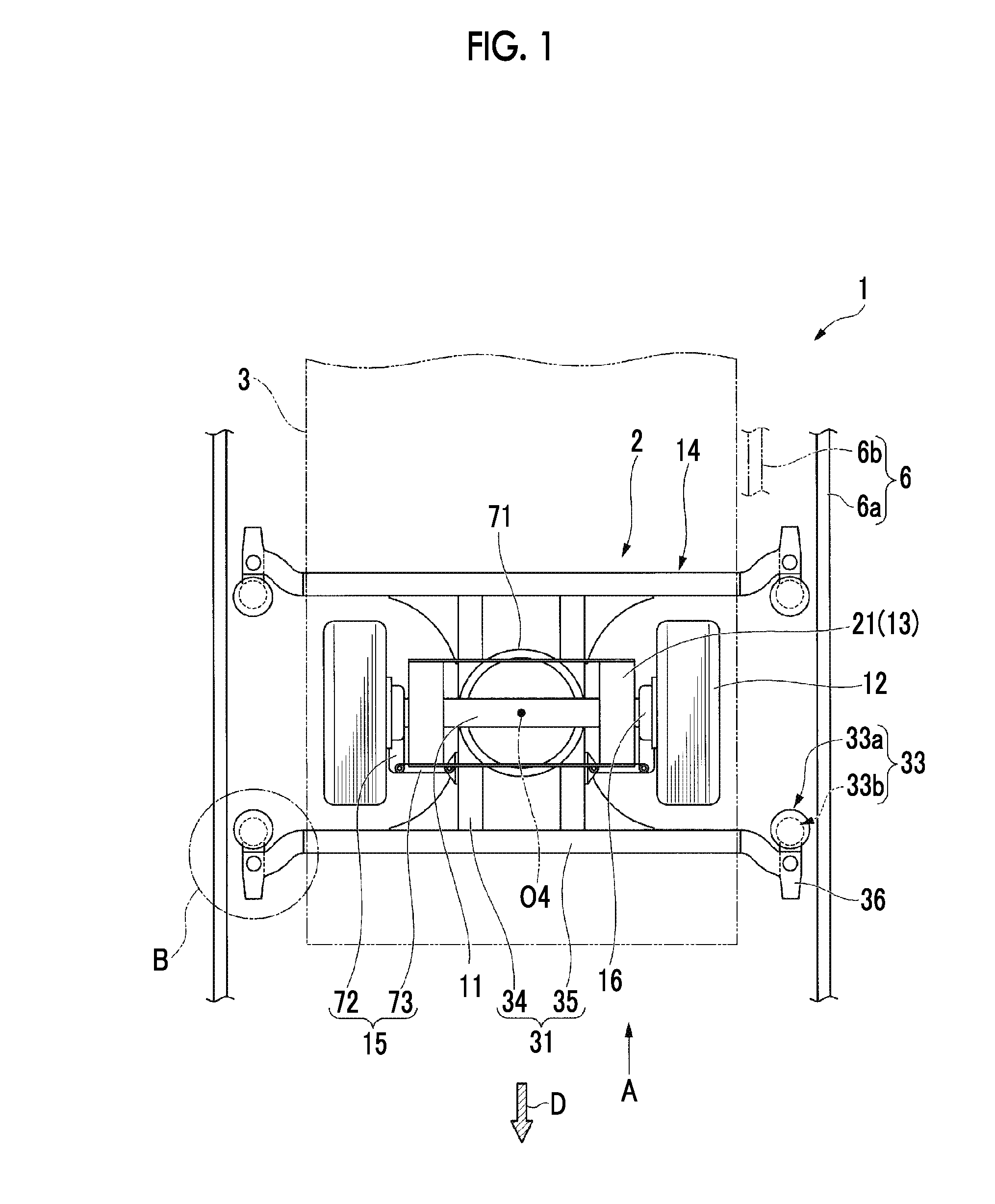
[0051]As shown in FIGS. 1 and 2, a vehicle 1 is a vehicle of a track based transportation system, which travels on a track 5 (refer to FIG. 2) while being guided by guide rails 6 provided at the track 5. In this embodiment, the vehicle 1 is a vehicle of a lateral guide rail type (side guide type) transportation system in which the guide rails 6 extending along an extending direction of the track 5 are provided on both sides in a width direction of the track 5.

[0052]Further, the guide rail 6 is provided with a main guide rail 6a disposed on each of both sides of the track 5, and a switching guide rail 6b which is provided at a switching section, at which the track 5 branches, and is located below the main guide rail 6a. In addition, the switching guide rail 6b is disposed only at the switching section of the track 5. However, in the illustrated example, for convenience, the switching guide rail 6b is shown by a chain line.

[0053]

[0054]The vehicle 1 is provided with a steering bogie 2 ...

second embodiment

[0097]Next, a second embodiment of the present invention will be described. This embodiment is different from the above-described first embodiment in that the wear indicator is formed at the tread section 61. In addition, in the following description, the same configurations as those in the above-described first embodiment are denoted by the same reference numerals and description is omitted.

[0098]As shown in FIG. 9, a wear indicator 200 of this embodiment is provided with a plurality of hole portions 201a and 201b recessed inward in the radial direction in the tread section 61 of the main guide wheel 33a. The hole portions 201a and 201b include a first hole portion 201a, and a second hole portion 201b in which a depth along the radial direction is shallower than that of the first hole portion 201a. The first hole portion 201a and the second hole portion 201b are alternately arranged to be spaced apart from each other in each of the axial direction and the circumferential direction....

modification example

[0101]In addition, in the second embodiment described above, a configuration in which the wear indicator 200 is provided with the plurality of hole portions 201a and 201b in which the depths along the radial direction are different has been described. However, the configuration of the wear indicator 200 is not limited thereto. For example, as shown in FIG. 10, a hole portion 202 in which an inner diameter varies as it goes inward in the radial direction may be configured as a wear indicator 203.

[0102]Specifically, the hole portion 202 shown in FIG. 10 is made as a stepped hole in which an inner diameter is gradually reduced as it goes inward in the radial direction, and has a large-diameter portion 202a, and a small-diameter portion 202b continuously provided on the inside in the radial direction in the large-diameter portion 202a. Then, the hole portions 202 are formed at intervals in the circumferential direction and the axial direction in the tread section 61. Further, in the ill...


PUM


Abstract

A guide wheel (33) for guiding a vehicle along a track is equipped with an annular tread section (61) that comes into contact with a guide rail extending along the track and a pair of sidewall sections (62) that are formed continuing from both edges of the tread section (61) in the axial direction and extend inward in the radial direction, said guide wheel (33) being characterized in that protrusions (63a, 63b) are formed over the entire circumference of each of the sidewall sections (62).

Description

TECHNICAL FIELD[0001]The present invention relates to a guide wheel, a steering bogie, and a vehicle.[0002]Priority is claimed based on Japanese Patent Application No. 2013-257453, filed on Dec. 12, 2013, the content of which is incorporated herein by reference.BACKGROUND ART[0003]As new transportation means other than a bus or a railroad, a track based transportation system which travels on a track by running wheels each composed of a rubber tire or the like is known. Such a track based transportation system is generally called a new transportation system or an automated people mover (APM).[0004]A vehicle of this kind of track based transportation system is provided with running wheels connected to an axle, and a steering guide device having guide wheels which roll in contact with guide rails provided along a track, and is made such that the guide wheels of the steering guide device are guided by the guide rails, whereby the respective running wheels are steered and travel on the t...

Claims


Application Information

Patent Timeline
Patent Type & Authority Applications(United States)
IPC IPC(8): B60C11/24B61B13/00B61F9/00B60C7/00B61F5/50
CPCB60C11/24B60C7/00B60C2019/006B61F9/00B61B13/00B61F5/50B60C11/032B60C13/02
Inventor KATAHIRA, KOUSUKETAMURA, SOHOSHI, MITSUAKI
Owner MITSUBISHI HEAVY IND ENG LTD
Why Eureka
Try Eureka