
Rope terminal arrangement and an elevator

a terminal arrangement and elevator technology, applied in the direction of elevators, transportation and packaging, mechanical equipment, etc., can solve the problems of difficulty in simple and reliable grip, loss of suspension of particular ropes, and special ropes which may be damaged, so as to reduce risks, simplify and optimize manufacturing processes, and reduce risks.

Inactive Publication Date: 2016-12-08
KONE CORP
View PDF2 Cites 23 Cited by
  • Summary
  • Abstract
  • Description
  • Claims
  • Application Information

AI Technical Summary

Benefits of technology

The invention provides a rope terminal solution for elevators that improves reliability. The solution includes a gripping device that can alleviate risks related to creep of rope gripping. The gripping device has a movable gripping face that narrows the gap between the rope section and the gripping device, causing compression on the rope section. The solution is simple and cost-effective, and can be used with ropes that tolerate sharp bends. The solution also includes a reinforcing fiber load bearing member that has a high tensile stiffness and longitudinal stiffness, facilitating the longitudinal direction of the rope. Overall, the invention provides a reliable and efficient solution for fixing ropes in elevators.

Problems solved by technology

In prior art, such special ropes are known which may be damaged if sharp bends are caused in them.
The rope end should be firmly gripped such that it can't slide out of the compression gap, because this would mean that the suspension of the particular rope would be lost.
This kind of rope terminal arrangement has the drawback that a reliable grip is difficult to provide simply.
The surface material is subjected to continuous compression and shear stress, which may cause increasing deformation over time (creep).
In long term, the creep phenomenon can lead to slipping which might result, in the worst case, in unexpected loss of suspension of the particular rope fixed by the rope terminal solution.
A drawback of the existing termination solutions has been that they have been difficult to design for producing good reliability with simple and cost-effective structure, in particular such that creep is prevented.

Method used


Image

  • Rope terminal arrangement and an elevator
  • Rope terminal arrangement and an elevator
  • Rope terminal arrangement and an elevator

Examples


Embodiment Construction

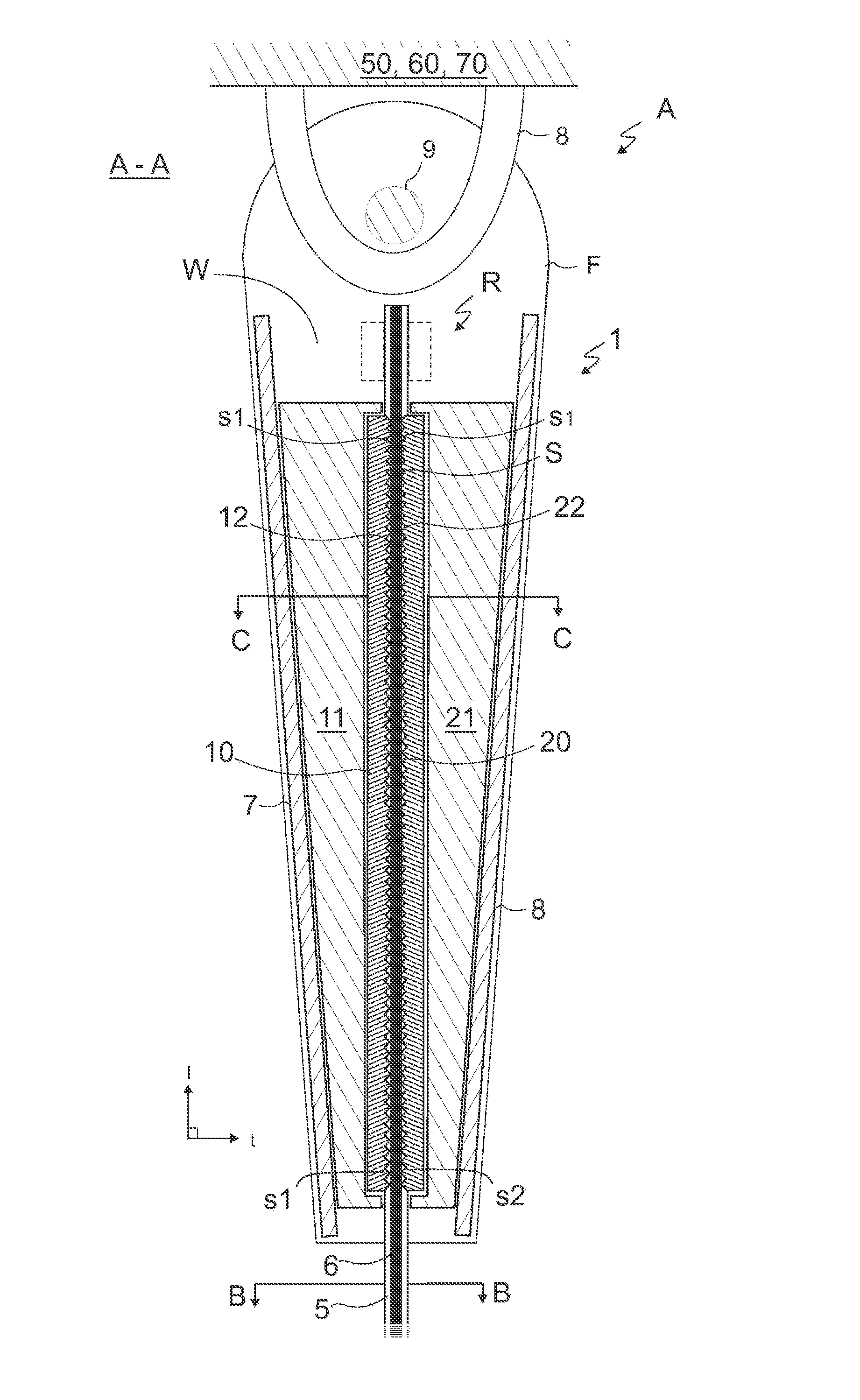
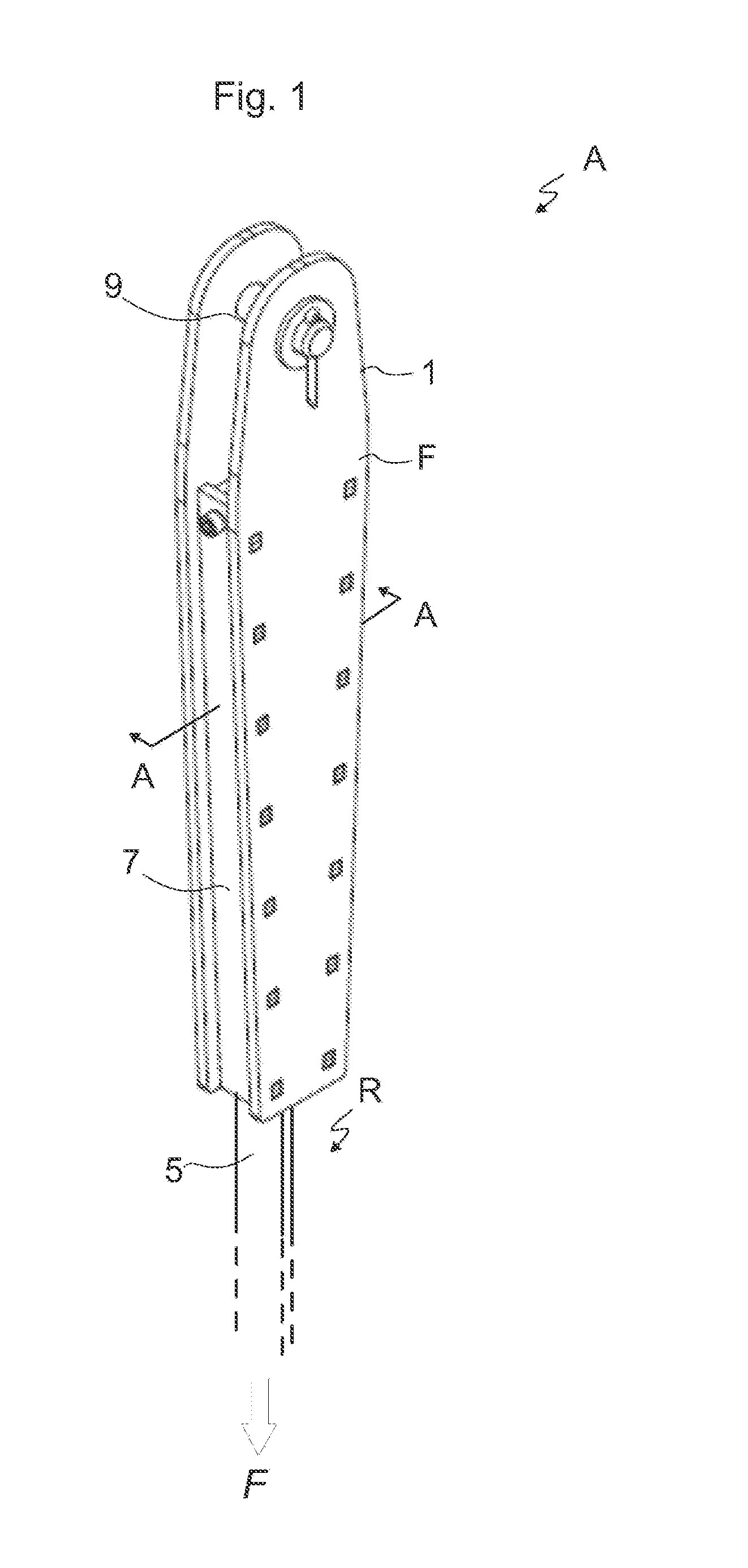
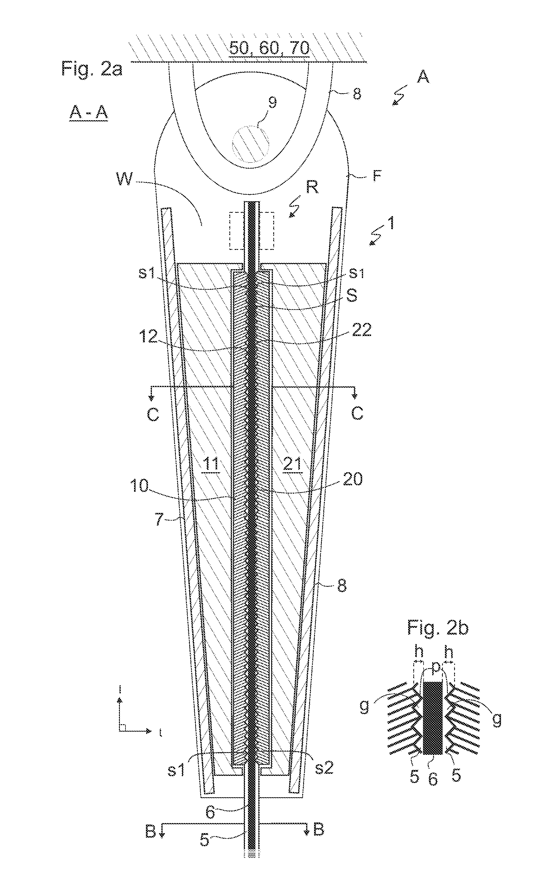
[0047]FIG. 1 illustrates an embodiment of a rope terminal arrangement A fixing an end of a hoisting rope R of the elevator immovably to a fixing base 50,60,70 (not showed). FIG. 2 illustrates a cross section A-A of the rope terminal arrangement A of FIG. 1. The rope terminal arrangement A comprises a belt-shaped rope R, and a gripping device 1 arranged to grip a rope section S of the belt-shaped rope R via first and second gripping face 12,22 facing each other and set against opposing first and second side of the rope section S placed in a gap between the first and second gripping face 12,22. The gripping faces 12,22 are movable at least slightly relative to each other such that the gap between them is at least slightly narrowed so as to cause compression on the rope section placed in the gap between them. The gripping device 1 further comprises a wedge frame F comprising a first side wall 7 and second side wall 8, which are at an acute angle relative to each other and delimiting a ...


PUM

PropertyMeasurementUnit
heightaaaaaaaaaa
surface patternaaaaaaaaaa
contact areaaaaaaaaaaa

Abstract

A rope terminal arrangement of an elevator includes a belt-shaped hoisting rope, and a gripping device arranged to grip a rope section of the belt-shaped rope via first and second gripping face facing each other and set against opposing first and second side of the rope section placed in a gap between them, the gripping device including a wedge frame delimiting a wedge-shaped space wherein said rope section is placed; and a first gripping member in the wedge shaped space, the first gripping member having said first gripping face set against the first side of said rope section, said first gripping face being provided with an uneven surface pattern for facilitating grip between said first gripping face and said first side of the rope section; and a first wedge member wedged in the wedge shaped space between the wedge frame and the first gripping member such that it wedges the first gripping member to press with said first gripping face against the first side of the rope section. An elevator includes said rope terminal arrangement.

Description

FIELD OF THE INVENTION[0001]The invention relates to fixing of elevator ropes, more specifically to a rope terminal arrangement for fixing an end of a rope of an elevator to a fixing base as well as to an elevator comprising said rope terminal arrangement. Said elevator is preferably suitable for transporting passengers and / or goods.BACKGROUND OF THE INVENTION[0002]In elevators, it is common that ropes are used as the means by which the elevator car is suspended. Ropes are further used as the means by which motive force is transmitted to the elevator car. Each rope end needs to be fixed to a fixing base, which is typically either the load to be lifted or a stationary structure, depending on the type of suspension chosen for the elevator. The rope ends can be fixed directly to the load, such as the car or counterweight, which is the case when these are to be suspended with 1:1 ratio. Alternatively, the rope ends can be fixed to a stationary structure of the building, which is the cas...

Claims


Application Information

Patent Timeline
Patent Type & Authority Applications(United States)
IPC IPC(8): B66B7/08B66B7/06
CPCB66B7/085B66B9/00B66B7/062B66B7/06F16G9/00F16G9/04
Inventor LEHTINEN, HANNUHALLIKAINEN, PEKKA
Owner KONE CORP
Learn More