Finger detection with auto-baseline tracking

a fingerprint and auto-baseline technology, applied in the field of electronic sensing, can solve problems such as unnecessarily consuming power

Active Publication Date: 2016-12-08
SYNAPTICS INC
View PDF11 Cites 56 Cited by
  • Summary
  • Abstract
  • Description
  • Claims
  • Application Information

AI Technical Summary

Benefits of technology

[0007]One embodiment provides a processing system for automatically tracking a baseline input into a biometric sensor. The processing system includes an amplifier having at least one input terminal and an output terminal for producing an output signal based on at least one input signal received by the at least one input terminal. The processing system further includes at least one signal conditioning element coupled to the at least one input terminal of the amplifier and configured to condition at least one compensation signal. And the processing system further includes a control circuit that adjusts one or more signal conditioning parameters of the at least one signal conditioning element based on the output signal of the amplifier. Wherein the at least one input signal received by the input terminal includes a combination of the at least one compensation signal and a signal from a first set of one or more receiver electrodes of the biometric sensor.
[0008]Another embodiment includes an electronic system for capacitive sensing. The electronic system includes a capacitive sensor configured to capacitively sense an input object in proximity to a plurality of electrodes. Wherein the plurality of electrodes includes a first set of one or more transmitter electrodes capacitively coupled to a first set of one or more receiver electrodes and forming a first signal path for a first sensor input signal. The plurality of electrodes further includes a second set of one or more transmitter electrodes capacitively coupled to a second set of one or more receiver electrodes and forming a second signal path for a second sensor input signal with opposite phase to the first sensor input signal. The electronic system further includes a processing system configured for automatically tracking a baseline value of the first input signal and the second input signal. The processing system includes a first compensation path including a first signal conditioning element, wherein the first compensation path transmits a first compensation signal. The processing system further includes a second compensation path including a second signal conditioning element, wherein the second compensation path transmits a second compensation signal with opposite phase to the first compensation signal. The electronic system further includes an amplifier including a first input terminal, a second input terminal and an output terminal, wherein the first sensor input signal and the first compensation signal are combined into a first amplifier input signal input on the first input terminal and the second sensor input signal and the second compensation signal are combined into a second amplifier input signal input on the second input terminal, and the output terminal produces an output signal based on the first amplifier input signal and the second amplifier input signal. The electronic system further includes a control circuit configured to adjust one or more signal conditioning parameters of the first signal conditioning element and the second signal conditioning element.
[0009]Yet another embodiment includes a processing system for automatically tracking a baseline input into a sensor. The processing system includes an amplifier having at least one input terminal and an output terminal for producing an output signal based on at least one input signal received by the at least one input terminal. The processing system further includes at least one signal conditioning element coupled to the at least one input terminal of the amplifier and configured to condition at least one compensation signal. The processing system further includes a control circuit that adjusts one or more signal conditioning parameters of the at least one signal conditioning element based on the output signal of the amplifier. The processing system further includes at least one comparator configured to compare the output signal to at least one baseline threshold. Wherein the control circuit adjusts the one or more signal conditioning parameters in a first direction when the output signal is higher than the at least one baseline threshold and adjusts the one or more signal conditioning parameters in a second direction when the output signal is lower than the at least one baseline threshold. Wherein the at least one input signal received by the input terminal includes a combination of the at least one compensation signal and a signal from a first set of one or more receiver electrodes of the sensor.

Problems solved by technology

Constantly scanning a fingerprint sensor array to capture an image may unnecessarily consume power when there is no corresponding fingerprint to be imaged.

Method used


Image

  • Finger detection with auto-baseline tracking
  • Finger detection with auto-baseline tracking
  • Finger detection with auto-baseline tracking

Examples


Embodiment Construction

[0024]The following detailed description is merely exemplary in nature and is not intended to limit the invention or the application and uses of the invention. Furthermore, there is no intention to be bound by any expressed or implied theory presented in the preceding technical field, background, brief summary or the following detailed description.

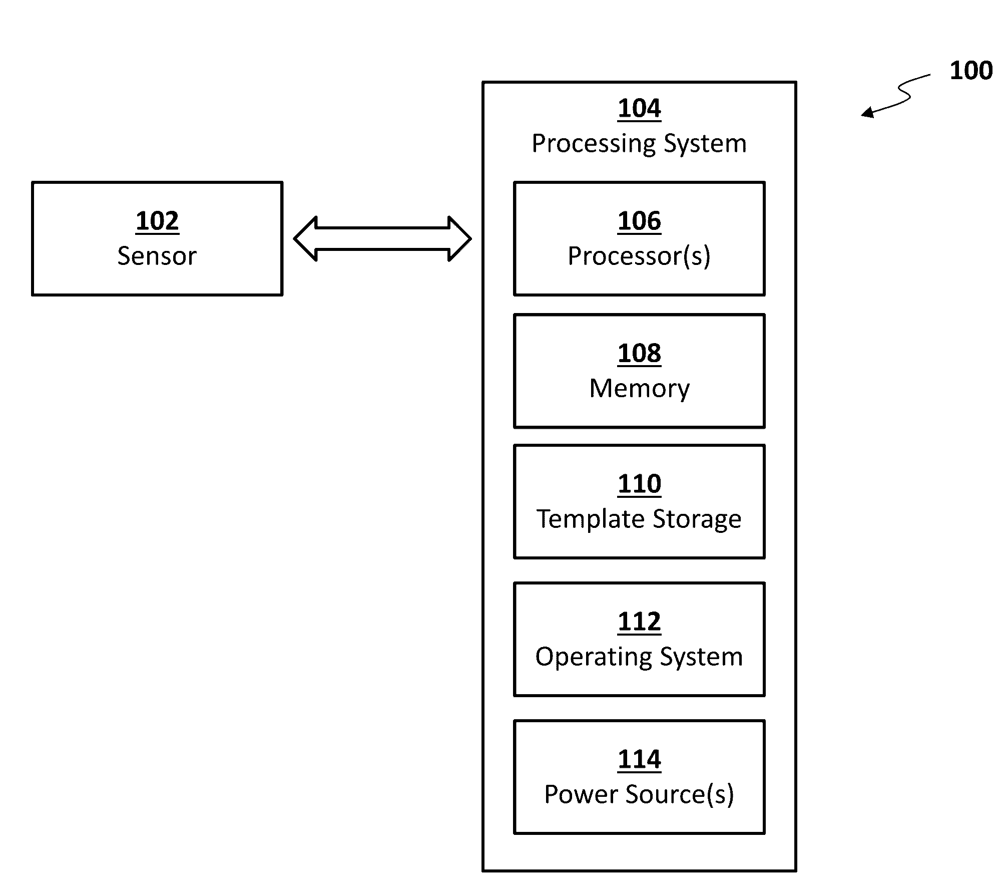
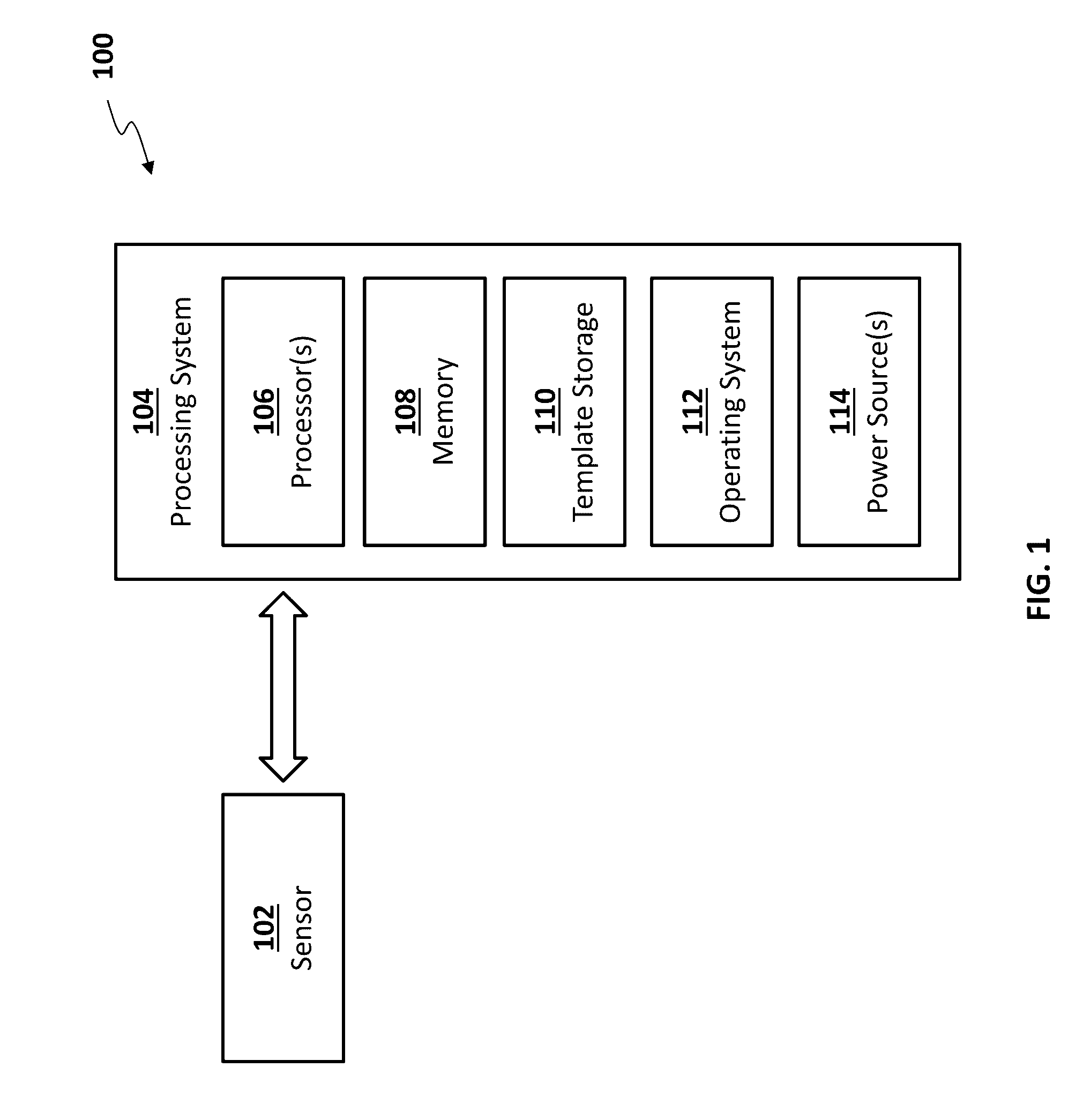
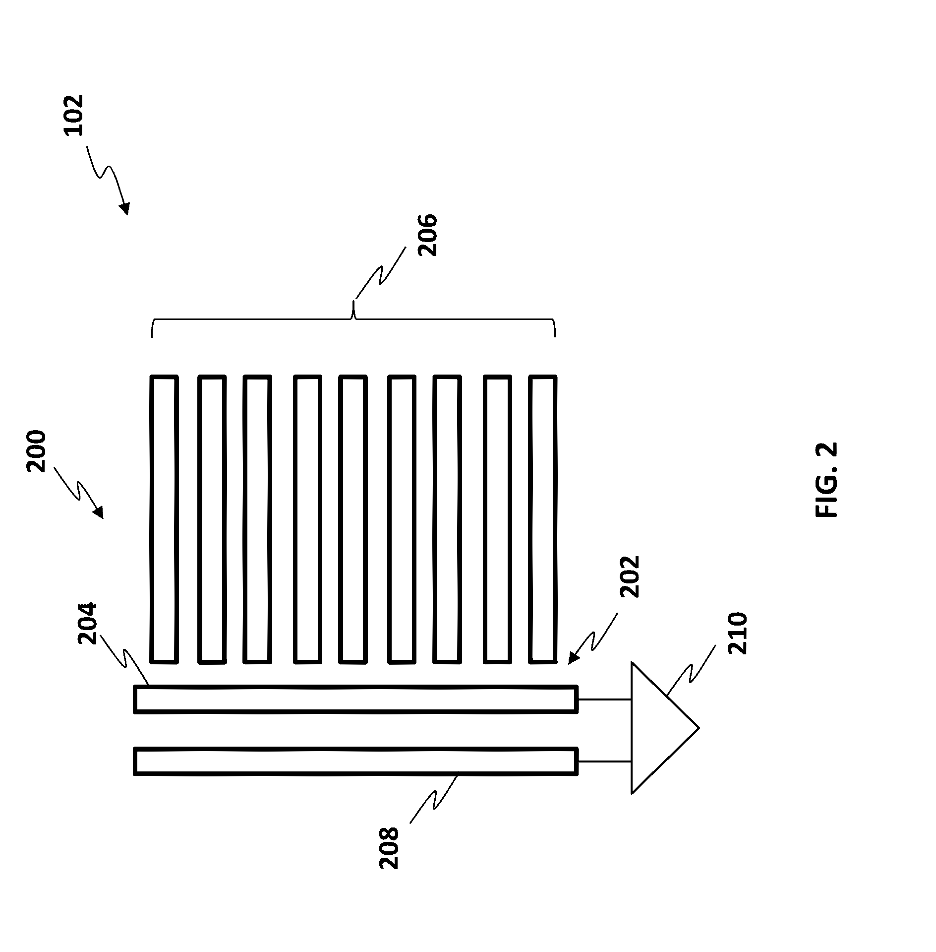
[0025]One way to detect presence of a finger or other input object is to use one or more dedicated presence sensing elements on the input device. For example, in a fingerprint sensor, finger presence sensing electrodes may be used in addition to the electrodes of a sensing array that are used to capture an image of a fingerprint in a sensing region of the input device.

[0026]Another way to detect presence of a finger or other input object is to re-use selected sensor electrodes of the sensor array as presence sensing electrodes for presence detection. This embodiment may allow space to be saved by avoiding a need for dedicated presence sens...


PUM


Abstract

A device and system for automatically tracking a baseline input into a biometric sensor is provided. The device and system include a processing system with an amplifier having an input terminal and an output terminal for producing an output signal based on the input signal received by the input terminal. The processing system further includes at least one signal conditioning element coupled to the input terminal of the amplifier and configured to condition a compensation signal, and the processing system further includes a control circuit that adjusts one or more signal conditioning parameters of the at least one signal conditioning element based on the output signal of the amplifier. The at least one input signal received by the input terminal includes a combination of the at least one compensation signal and a signal from a first set of one or more receiver electrodes of the biometric sensor.

Description

CROSS-REFERENCE TO RELATED APPLICATIONS[0001]This application claims priority to U.S. provisional patent application Ser. No. 62 / 171,718, to Gordon Shen, et al., filed on Jun. 5, 2015, entitled “FINGER DETECTION WITH AUTO-BASELINE TRACKING,” the entire contents of which are herein incorporated by reference.FIELD OF DISCLOSURE[0002]This invention generally relates to electronic sensing, and more particularly, to capacitive fingerprint sensing.BACKGROUND OF THE INVENTION[0003]Biometric authentication systems are used for authenticating users of devices incorporating the authentication systems. Among other things, biometric sensing technology can provide a reliable, non-intrusive way to verify individual identity for authentication purposes.[0004]Fingerprints, like various other biometric characteristics, are based on unalterable personal characteristics and thus are a reliable mechanism to identify individuals. There are many potential applications for utilization of biometric and fin...

Claims


Application Information

Patent Timeline
Patent Type & Authority Applications(United States)
IPC IPC(8): G06K9/00
CPCG06K9/0002G06V40/1306G06F3/044G06F3/0418
Inventor SHEN, GUOZHONGERDOGAN, OZANSCHWARTZ, ADAM L.MACKEY, BOB LEEKULKARNI, MANDARLIEN, TYWANG, NAN
Owner SYNAPTICS INC
Why Eureka
Try Eureka