
Loudspeaker

a loudspeaker and speaker technology, applied in the field of loudspeakers, can solve the problems of affecting the output of other amplifiers, affecting the quality of the sound, and the temperature of the amplifier, so as to prevent damage to the electrical part and the effect of preventing the damag

Active Publication Date: 2016-12-15
FUJITSU GENERAL LTD
View PDF6 Cites 3 Cited by
  • Summary
  • Abstract
  • Description
  • Claims
  • Application Information

AI Technical Summary

Benefits of technology

The invention describes a technology to prevent damage to electrical parts in a loudspeaker caused by two different systems. This is achieved by using a resistor with a higher impedance than the internal resistance of the loudspeaker, which prevents current from flowing from the first amplifier to the second amplifier. The goal is to protect the electrical part from damage and ensure proper functioning of the loudspeaker.

Problems solved by technology

However, when only one of the two power amplifiers connected in parallel outputs the audio signals, an impedance of the other amplifier not outputting audio signals becomes lower.
In this case, overcurrent may be generated in the both power amplifiers so that temperature thereof may rise or an electronic part thereof may be damaged.

Method used


Image

  • Loudspeaker
  • Loudspeaker
  • Loudspeaker

Examples


first embodiment

1. First Embodiment

[0020]

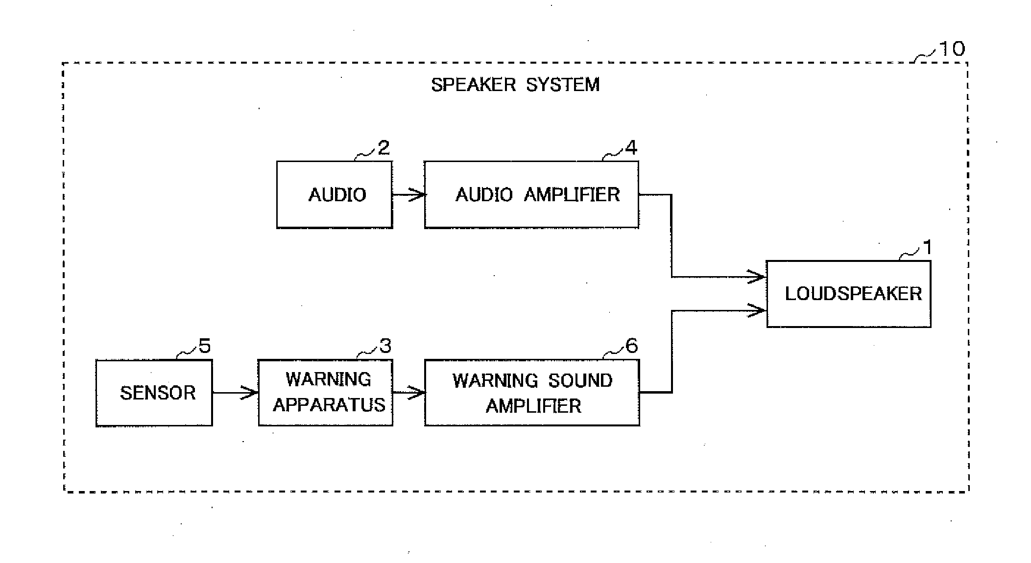
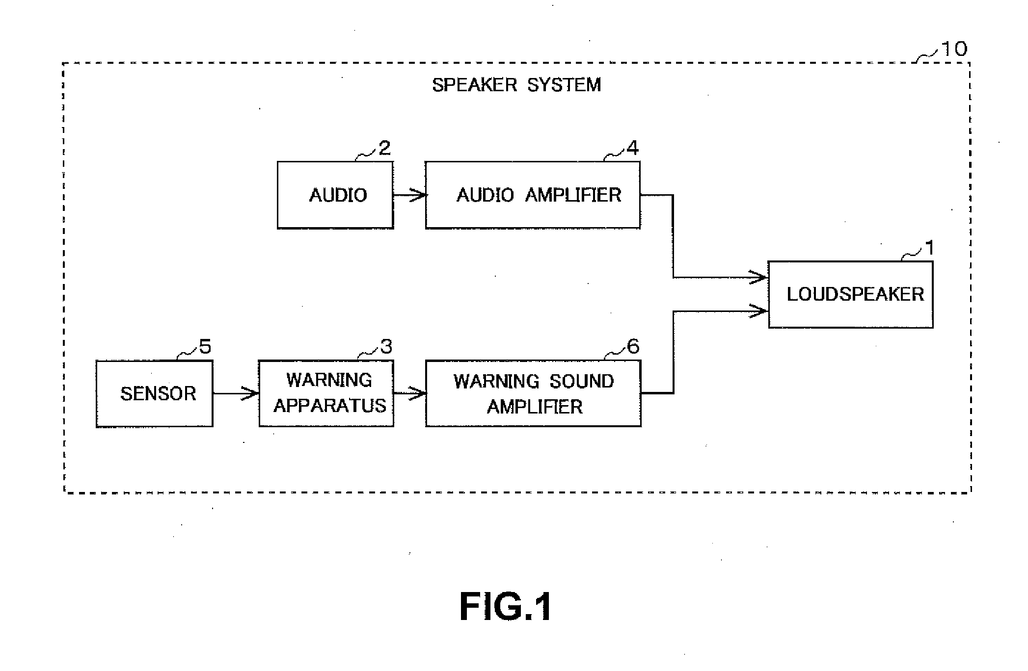
[0021]First, an outline of a first embodiment of the invention will be described. FIG. 1 illustrates a configuration of a speaker system 10 including a loudspeaker 1. The speaker system 10 is mounted, for example, on a vehicle and is a system that outputs, from the loudspeaker 1, a sound generated by an audio 2 and a warning sound generated by a warning apparatus 3, to a driver of the vehicle.

[0022]The loudspeaker 1 is embedded on a side or another portion of a cabin of the vehicle and outputs music and the like to the driver of the vehicle.

[0023]The audio 2 (audio apparatus) generates an audio signal indicative of sounds of music, radio, route guidance, etc. The audio 2 causes the generated audio signal to be amplified by an audio amplifier 4 and then outputs the amplified audio signal from the loudspeaker 1. The audio 2 is, for example, a CD player, a tuner or a car navigation system.

[0024]Once receiving a signal from a sensor 5, for example, a lane depart...

second embodiment

2. Second Embodiment

[0065]

[0066]Next, a second embodiment of the invention will be described below. FIG. 5 illustrates a speaker system 10 including a loudspeaker 1 in the second embodiment. The loudspeaker 1 of the foregoing first embodiment includes the first input portion 11 and the second input portion 12. However, the second embodiment includes a resistance box 7 placed between the loudspeaker 1 and an audio amplifier 4 and also placed between the loudspeaker 1 and a warning sound amplifier 6. The resistance box 7 includes a first transmission system and a second transmission inside. In other words, the resistance box 7 is a connector including a resistor. The resistance box 7 is used to simplify a configuration of the loudspeaker 1. The second embodiment includes similar configuration portions to the first embodiment. Therefore, differences from the first embodiment will be mainly described below.

[0067]

[0068]FIG. 6 illustrates a configuration of the resistance box 7. The resis...


PUM


Abstract

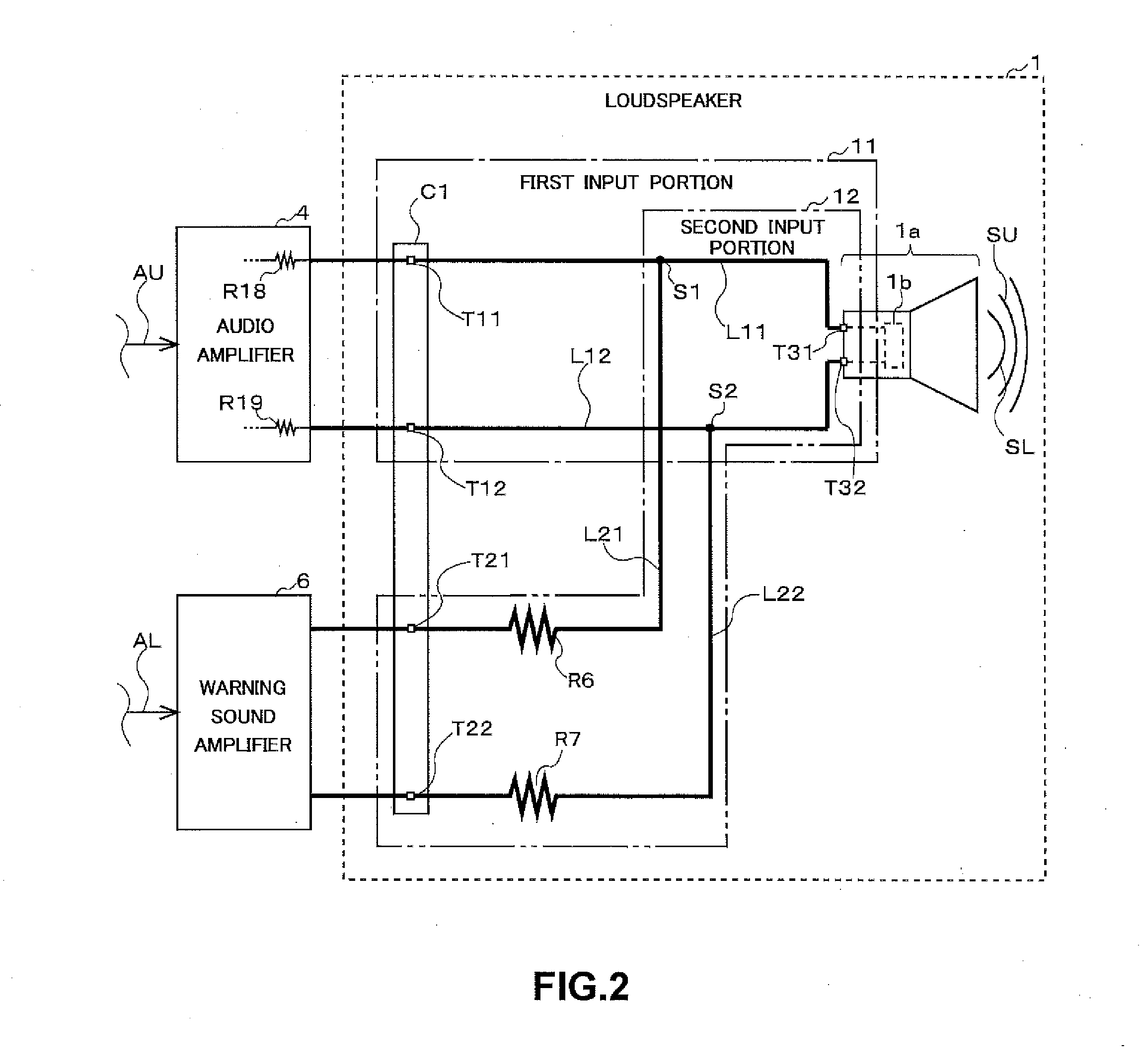
An audio amplifier and a warning sound amplifier are connected in parallel to each other, relative to a voice coil of a loudspeaker. A resistor having an impedance greater than an impedance of the voice coil is connected to the voice coil and is also connected to the warning sound amplifier. An audio signal from the warning sound amplifier is input to the voice coil via the resistor. Thus, since the warning sound amplifier is connected to the resistor having the impedance greater than the impedance of the voice coil of the loudspeaker, even in a case where only the audio amplifier is operated, a large current is prevented from flowing into the warning sound amplifier.

Description

BACKGROUND OF THE INVENTION[0001]Field of the Invention[0002]The invention relates to a technology for a loudspeaker having a plurality of audio signal input systems.[0003]Description of the Background Art[0004]Conventionally, some loudspeakers have a plurality of audio signal input systems. One among those loudspeakers is a loudspeaker to which audio signals for music and the like and signals for warning sounds are input. Such a loudspeaker includes two power amplifiers connected in parallel.[0005]However, when only one of the two power amplifiers connected in parallel outputs the audio signals, an impedance of the other amplifier not outputting audio signals becomes lower. Therefore, large current may flow into the other amplifier. In this case, overcurrent may be generated in the both power amplifiers so that temperature thereof may rise or an electronic part thereof may be damaged.SUMMARY OF THE INVENTION[0006]According to one aspect of the invention, a loudspeaker includes: a v...

Claims


Application Information

Patent Timeline
Patent Type & Authority Applications(United States)
IPC IPC(8): H04R3/00H03F3/20H03F3/181H04R9/06
CPCH04R3/007H04R9/06H04R2499/13H03F3/181H03F3/20H03F2200/426H03F2200/447H03F1/52
Inventor TANAKA, KEIICHIROKATO, SHIGEKI
Owner FUJITSU GENERAL LTD
Learn More