Drive unit for hybrid vehicle

a hybrid vehicle and drive unit technology, applied in mechanical equipment, transportation and packaging, gearing, etc., can solve the problem of not being able to generate a torque for propelling the vehicl

Active Publication Date: 2016-12-22
TOYOTA JIDOSHA KK
View PDF0 Cites 32 Cited by
  • Summary
  • Abstract
  • Description
  • Claims
  • Application Information

AI Technical Summary

Benefits of technology

[0017]In addition, according to the embodiment in which a single-pinion planetary gear unit is used individually as the first and the second planetary gear units, and in which the first clutch and the second clutch are arranged coaxially across the first planetary gear unit and the second planetary gear unit, the connection between the rotary members or the connection between the rotary member and the clutch, the first motor or the engine may be simplified to downsize the drive unit.

Problems solved by technology

In the hybrid drive unit of this kind, the first motor has to establish a reaction torque during generating the engine power and hence cannot be used to generate a torque for propelling the vehicle.

Method used


Image

  • Drive unit for hybrid vehicle
  • Drive unit for hybrid vehicle
  • Drive unit for hybrid vehicle

Examples


second embodiment

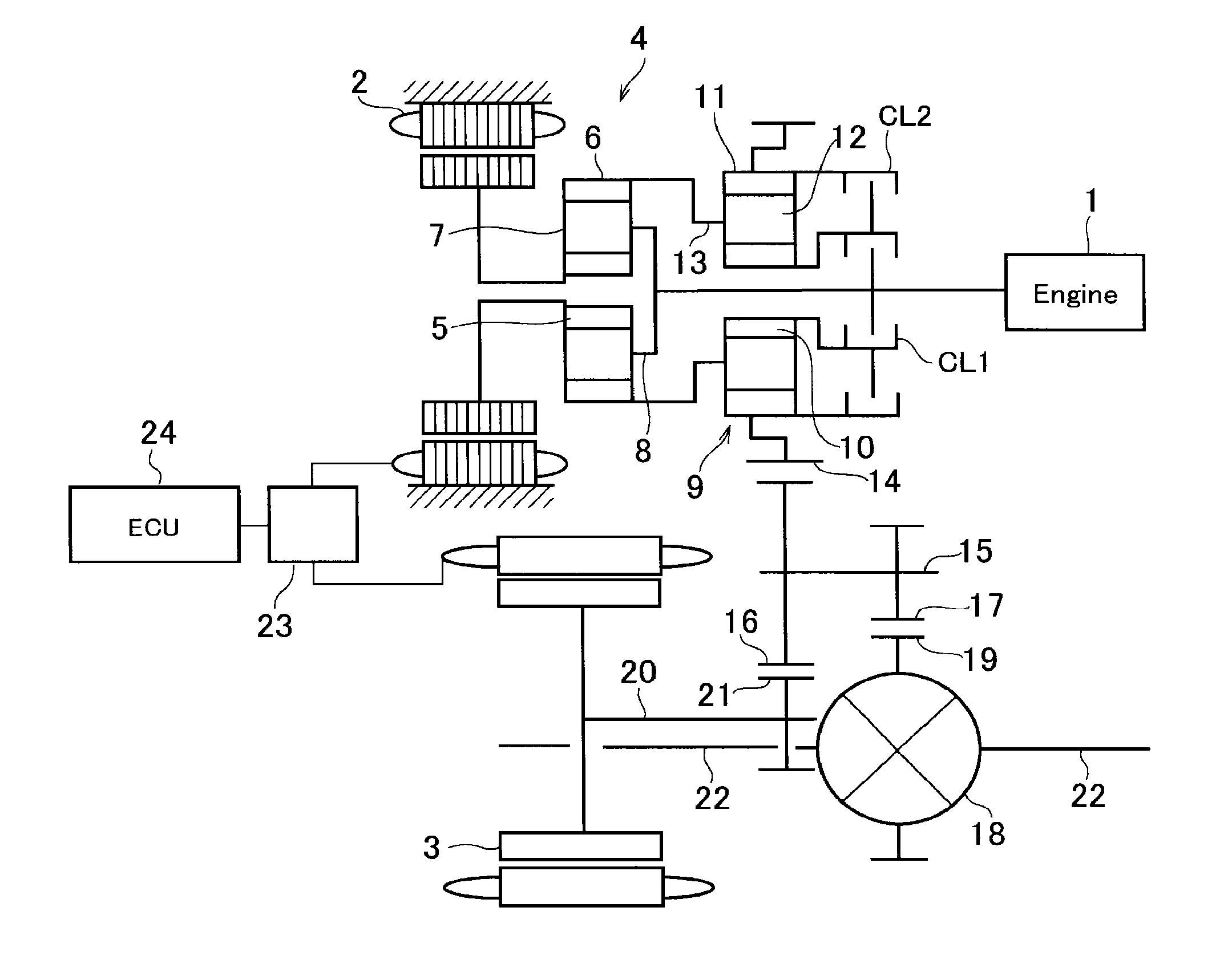
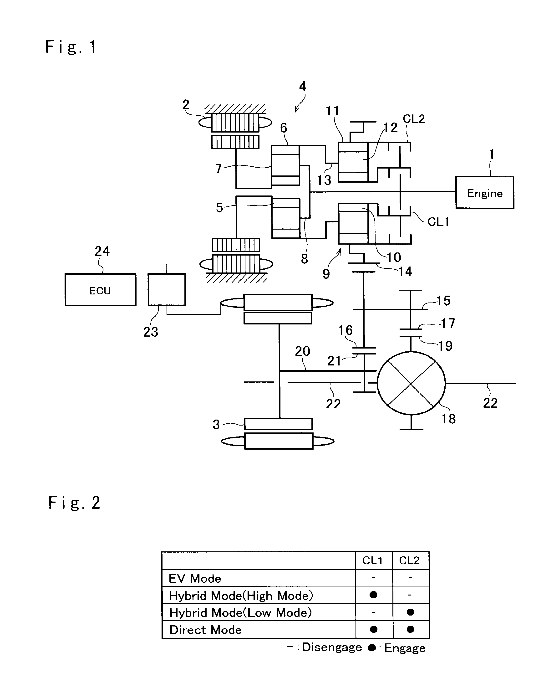
[0057]Thus, in the drive unit shown in FIG. 1, the power distribution device 4 and the second planetary gear unit 9 are combined to form the complex planetary gear unit to alter the power distribution ratio by connecting the first ring gear 6 to the second carrier 13 while connecting the first carrier 8 to the second sun gear 10. Turning to FIG. 10, there is shown the drive unit in which arrangements of the first clutch CL1 and the second clutch CL2 are altered to connect the power distribution device 4 to the second planetary gear unit 9.

[0058]According to the second embodiment shown in FIG. 10, the first ring gear 6 of the power distribution device 4 is connected to the second sun gear 10 of the second planetary gear unit 9. The first clutch CL1 is disposed between the power distribution device 4 and the first motor 2 to selectively connect the first carrier 8 of the power distribution device 4 to the second ring gear 11 of the second planetary gear unit 9. According to the second...

third embodiment

[0066]Turning to FIG. 16, there is shown a modification of the third embodiment shown in FIG. 14. In the drive unit shown in FIG. 16, the second sun gear 10a of the second planetary gear unit 9a is used as an output element, and the second carrier 13a of the second planetary gear unit 9a is connected to the first carrier 8 of the power distribution device 4. Accordingly, an output shaft 14a extending in the opposite direction to the engine 1 on which the second sun gear 10a is fitted serves as an output element. Although omitted in FIG. 16, a torque of the second motor 3 is applied to the output shaft 14a. That is, the drive unit shown in FIG. 16 is adapted to be applied to a front-engine, rear-wheel-drive layout vehicle (i.e., an FR layout vehicle). To this end, in the drive unit shown in FIG. 16, the first motor 2, the power distribution device 4, the second planetary gear unit 9a, the first clutch CL1, and the second clutch CL2 are arranged in a downstream side of the engine 1 in...

fourth embodiment

[0072]Turning to FIG. 19, there is shown a modification of the fourth embodiment shown in FIG. 17 that is adapted to be applied to an FR layout vehicle. In the drive unit shown in FIG. 19, the engine 1 is disposed on an opposite side to the first clutch CL1, the second clutch CL2, the second planetary gear unit 9 etc. across the first motor 2, and the output shaft 14a extends in the opposite direction to the engine 1 along the rotational center from the power distribution device 4a. Although omitted in FIG. 19, a torque of the second motor 3 is applied to the output shaft 14a.

[0073]In the drive unit shown in FIG. 19, an arrangement of the constitutional elements are altered based on the drive unit shown in FIG. 17. Accordingly, an operating mode of the drive unit shown in FIG. 17 may also be selected from the EV mode, the high mode of hybrid mode, the low mode of hybrid mode and the direct mode, and the speed ratio and the power distribution ratio under the hybrid mode is identical...


PUM


Abstract

A drive unit for a hybrid vehicle in which selectable operating modes are increased and power distribution ratio is changeable is provided. The drive unit comprises: a first planetary gear unit having a first input element to which power of an engine is applied, a first reaction element connected to a first motor, and a first output element; a second planetary gear unit that performs having a second input element connected to the first output element, a second output element connected to an output member, and a second reaction element; a first clutch that selectively connects any of the first input element and the first reaction element to the second reaction element; and a second clutch that selectively connects at least any of two elements of the second planetary gear unit to rotate the second planetary gear unit integrally.

Description

CROSS REFERENCE TO RELATED APPLICATIONS[0001]The present application claims the benefit of priority to Japanese Patent Application No. 2015-123158 filed on Jun. 18, 2015 with the Japanese Patent Office, the entire contents of which are incorporated herein by reference in its entirety.BACKGROUND[0002]Field of the Disclosure[0003]Embodiments of the present disclosure relate to the art of a drive unit having an engine and a motor, and especially to a hybrid drive unit having an engine and two motors or motor-generators.[0004]Discussion of the Related Art[0005]JP-A-2014-51146 describes one example of the hybrid drive unit of this kind. According to the teachings of JP-A-2014-51146, an engine and a first motor for controlling an engine speed are connected to rotary elements of a first planetary gear unit serving as a power distribution device, and a second planetary gear unit serving as a transmission for changing torque of an output element of the first planetary gear unit is connected ...

Claims


Application Information

Patent Timeline
Patent Type & Authority Applications(United States)
IPC IPC(8): B60K6/365F16H1/46B60K6/442B60K6/445B60K6/387B60W20/40
CPCB60K6/365B60K6/387B60W20/40Y10S903/912B60K6/445F16H1/46Y10S903/911B60K6/442B60W10/02B60W10/10B60W20/30B60W2710/021B60W2710/1005B60K2006/381F16H3/728F16H2037/0873F16H2200/2007F16H2200/2035Y02T10/62
Inventor ENDO, TAKAHITOIWASE, YUJINAGAI, HIDEKAZUHATA, KENSEI
Owner TOYOTA JIDOSHA KK
Why Eureka
Try Eureka