Light source device, illumination device, and projector

a technology of illumination device and light source, which is applied in the direction of picture reproducers using projection devices, instruments, lenses, etc., can solve the problems of low light use efficiency, difficult mounting error in the normal direction of the mounting surface, and inefficient use of solid-state light sources. achieve the effect of high light use efficiency

Active Publication Date: 2016-12-22
SEIKO EPSON CORP
View PDF4 Cites 19 Cited by
  • Summary
  • Abstract
  • Description
  • Claims
  • Application Information

AI Technical Summary

Benefits of technology

[0038]The projector according to the third aspect is equipped with the illumination device described above, and is therefore high in light use efficiency.

Problems solved by technology

However, in the illumination device described in Document 1 and the light source device described in Document 2, since the mounting variation of the solid-state light source is not taken into consideration, there is a problem that the light emitted from the solid-state light source is not efficiently used, and thus the light use efficiency decreases.
Thus, even in the case in which, for example, the mounting error of the light emitting element occurs, the secondary light source image of the light emitted from the light emitting element is unlikely to run off the second small lens.
Thus, even in the case in which, for example, the mounting error of the light emitting part occurs, the secondary light source image of the light emitted from the light emitting part is unlikely to run off the second small lens.
Further, since the plurality of light emitting parts is mounted on the mounting surface, the mounting error is difficult to occur in the normal direction of the mounting surface.
Therefore, even in the case in which the mounting error of the light emitting parts occurs in the first direction, the influence of the mounting error is relatively small.

Method used


Image

  • Light source device, illumination device, and projector
  • Light source device, illumination device, and projector
  • Light source device, illumination device, and projector

Examples


first embodiment

Projector

[0059]Firstly, an example of the projector 1 shown in FIG. 1 will be described.

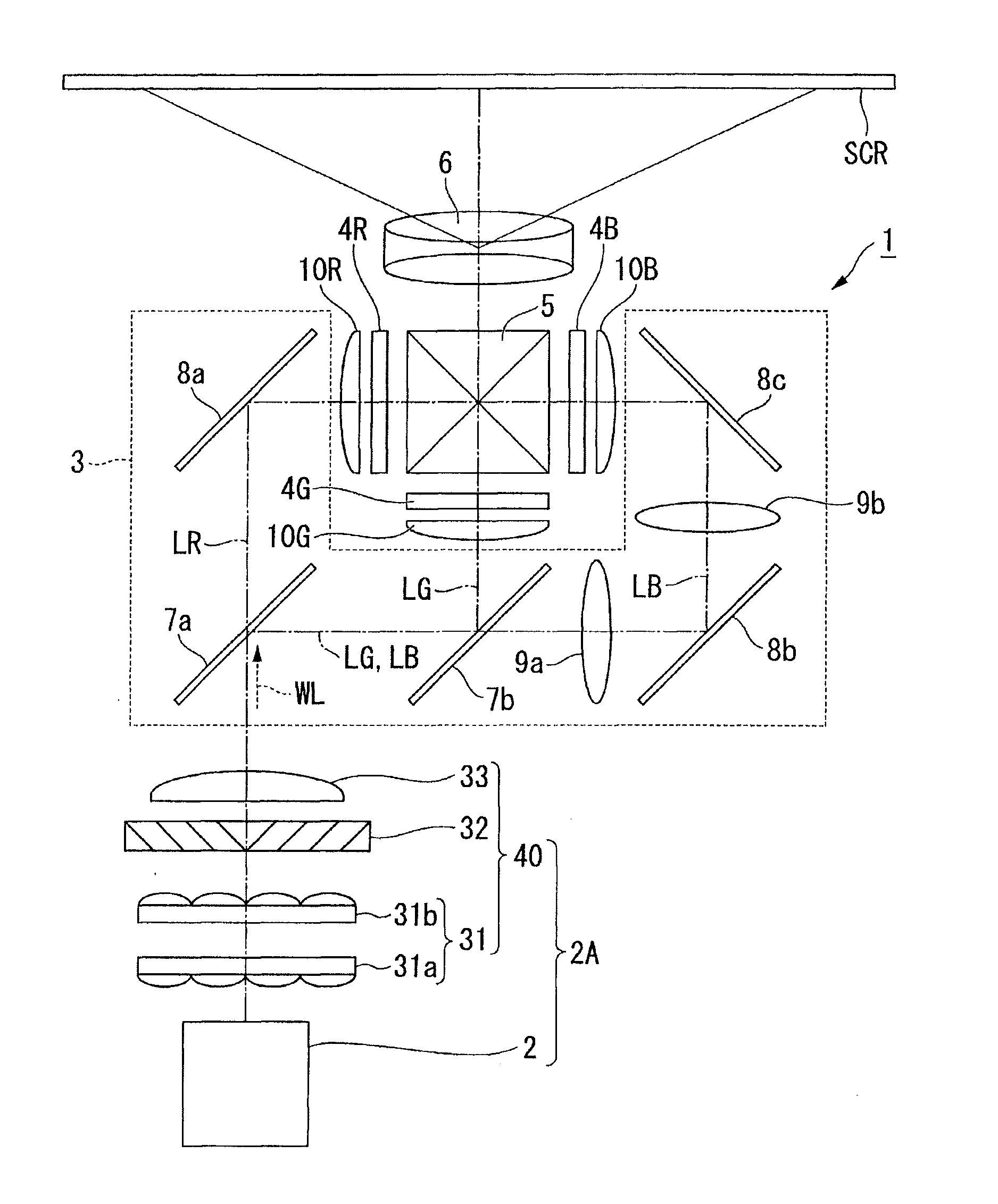
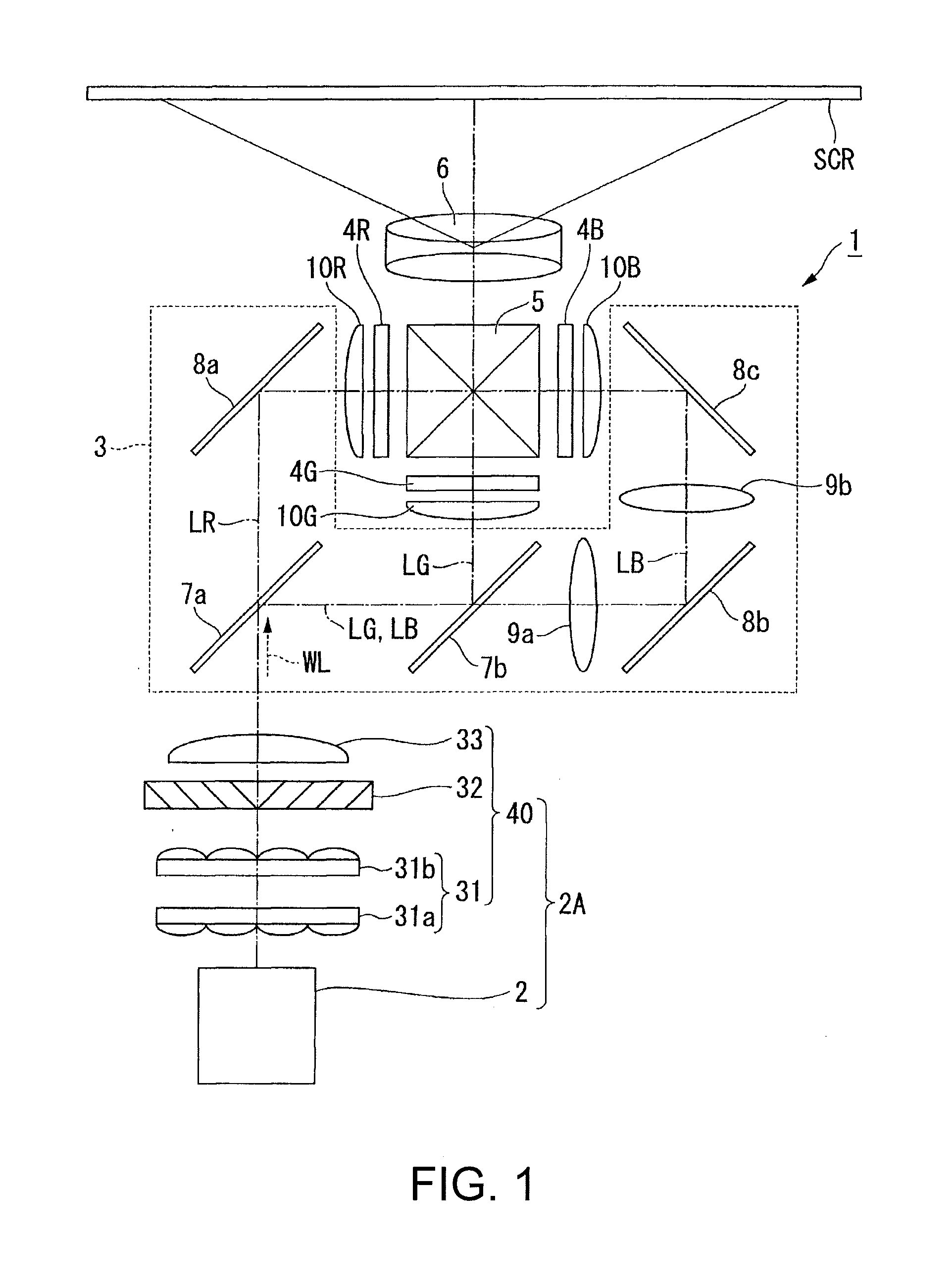
[0060]FIG. 1 is a plan view showing a schematic configuration of the projector 1.

[0061]The projector 1 according to the present embodiment is a projection-type image display device for displaying a color picture (image) on a screen (a projection target surface) SCR. The projector 1 uses three light modulation devices corresponding respectively to colored light, namely red light LR, green light LG, and blue light LB. The projector 1 uses semiconductor lasers (laser sources), with which high-intensity and high-power light can be obtained, as light sources of an illumination device.

[0062]Specifically, as shown in FIG. 1, the projector 1 is generally provided with the illumination device 2A, a color separation optical system 3, a light modulation device 4R, a light modulation device 4G, a light modulation device 4B, a combining optical system 5, and a projection optical system 6.

[0063]The illuminatio...

second embodiment

[0138]A homogenizer optical system according to a second embodiment will be described. It should be noted that configurations and members common to the embodiment described above and the present embodiment will be denoted by the same reference symbols, and the explanation thereof will be omitted, or simplified.

[0139]FIGS. 8A and 8B are diagrams showing a configuration of an essential part of the homogenizer optical system 224 of the present embodiment, wherein FIG. 8A is a plan view of the homogenizer optical system 224 viewed from the +Z direction, and FIG. 8B is a side view of the homogenizer optical system 224 viewed from the −Y direction.

[0140]The homogenizer optical system 224 of the present embodiment has a first lens array 224a and a second lens array 224b. The first lens array 224a includes a plurality of first small lenses 224am, and the second lens array 224b includes a plurality of second small lenses 224bm. It should be noted that the second lens array 224b has the same ...

third embodiment

[0147]A third embodiment will be described. It should be noted that configurations and members common to the embodiment described above and the present embodiment will be denoted by the same reference symbols, and the explanation thereof will be omitted, or simplified.

Projector

[0148]Firstly, an example of the projector 261 shown in FIG. 9 will be described.

[0149]FIG. 9 is a plan view showing a general configuration of the projector 261.

[0150]As shown in FIG. 9, the projector 261 is provided with an illumination device 262, a first total reflection mirror 267a, a second total reflection mirror 267b, a third total reflection mirror 7c, a dichroic mirror 8, the light modulation device 4R, the light modulation device 4G, the light modulation device 4B, the combining optical system 5, and the projection optical system 6.

[0151]The illumination device 262 emits the blue light LB as first illumination light, and yellow light YL as second illumination light.

[0152]The dichroic mirror 8 has a ...


PUM


Abstract

A light source device includes a light source array including at least one light emitting part, a collimating optical system that receives a light beam bundle emitted from the light source array, a first lens array including a plurality of first small lenses that receives the light beam bundle having passed through the collimating optical system, and a second lens array that is disposed in a subsequent stage of the first lens array and includes a plurality of second small lenses corresponding respectively to the first small lenses. The planar shape of the light emission area of the light emitting part has a short-side direction and a longitudinal direction. The planar shape of the second small lens has a longitudinal direction. The short-side direction of the light emission area crosses the longitudinal direction of the second small lens.

Description

BACKGROUND[0001]1. Technical Field[0002]The present invention relates to a light source device, an illumination device, and a projector.[0003]2. Related Art[0004]Projectors are devices for modulating light emitted from a light source part in accordance with image information using a light modulation device, and then projecting the image thus obtained in an enlarged manner using a projection lens. In recent years, a solid-state light source such as a semiconductor laser, with which high-intensity and high-power light can be obtained, attracts attention as a light source of a light source device used for such a projector.[0005]In JP-A-2013-15762 (Document 1), there is disclosed an illumination device for a projector, provided with an array light source having a plurality of semiconductor lasers arranged two-dimensionally, a pair of cylindrical lenses for collimating a light beam bundle of light emitted from the array light source, and an integrator optical system for homogenizing the ...

Claims


Application Information

Patent Timeline
Patent Type & Authority Applications(United States)
IPC IPC(8): H04N9/31G02B3/06G02B5/04G02B27/30
CPCH04N9/3152H04N9/3138H04N9/3161G02B5/04G02B27/30G02B3/06H04N9/3105G02B27/0905G02B27/0966G02B27/141G03B21/208
Inventor AKIYAMA, KOICHI
Owner SEIKO EPSON CORP
Why Eureka
Try Eureka