Passive power-conservative artificial knee

a passive, power-saving technology, applied in the field of artificial knee prosthetics and orthotics, can solve problems such as overuse injuries, and achieve the effects of reducing pain, reducing pain, and reducing pain

Active Publication Date: 2016-12-29
RGT UNIV OF CALIFORNIA
View PDF0 Cites 27 Cited by
  • Summary
  • Abstract
  • Description
  • Claims
  • Application Information

AI Technical Summary

Benefits of technology

[0008]The present invention is directed to a passive power-conservative artificial knee. In particular, the invention here describes an artificial knee and its applications in a variety of exoskeleton systems where a passive force generator (e.g., a spring actuator) is used to impede the knee flexion during early stance (an early portion of a stance phase). Energy during a portion of the stance phase is stored in the passive force generator and then released at late stance (a later portion of the stance phase) to provide sufficient flexion during swing (swinging of the leg) to clear the ground. The device is composed of a thigh link and a shank link rotatably coupled to each other at a knee joint. A passive compressive force generator (e.g., a gas spring actuator) is rotatably coupled to either the shank link or the thigh link from its first end. When the shank link is flexing toward the thigh link during stance (stance phase) and an angle of the shank link relative to the thigh link is less than a predetermined toggle angle, the force generator is becoming compressed (energy is stored) and resists the flexion of the shank link relative to the thigh link. When the shank link is flexing toward the thigh link and the angle of shank link relative to the thigh link is larger than the toggle angle, the compressive force generator becomes decompressed (energy is released) and therefore encourages the flexion of the shank link relative to the thigh link. When the force generator is substantially extended and the compressive force is substantially small toward the end of flexion during a swing phase, the force generator neither resists nor encourages the extension and flexion of the shank link from the thigh link. This means the shank link can freely extend during swing. The artificial knee described herein may be worn not only independently on a wearer's knee, but also in conjunction with hip, ankle or foot exoskeletons. This gives a great deal of flexibility for use of exoskeleton knees in a variety of medical, civilian and military applications.

Problems solved by technology

This locked posture results in patients' ability to ambulate with gait deviations that can lead to overuse injuries.

Method used


Image

  • Passive power-conservative artificial knee
  • Passive power-conservative artificial knee
  • Passive power-conservative artificial knee

Examples


Embodiment Construction

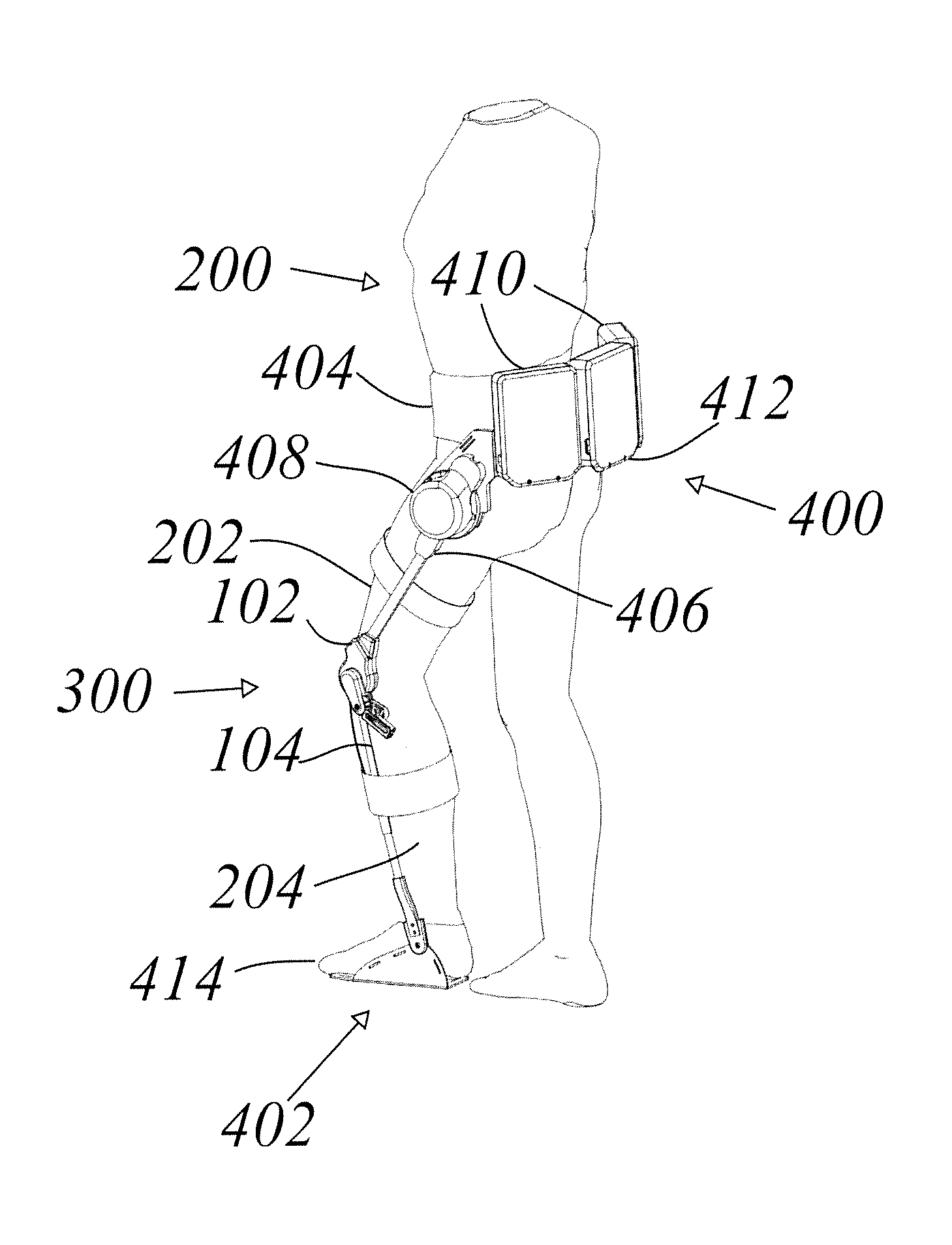
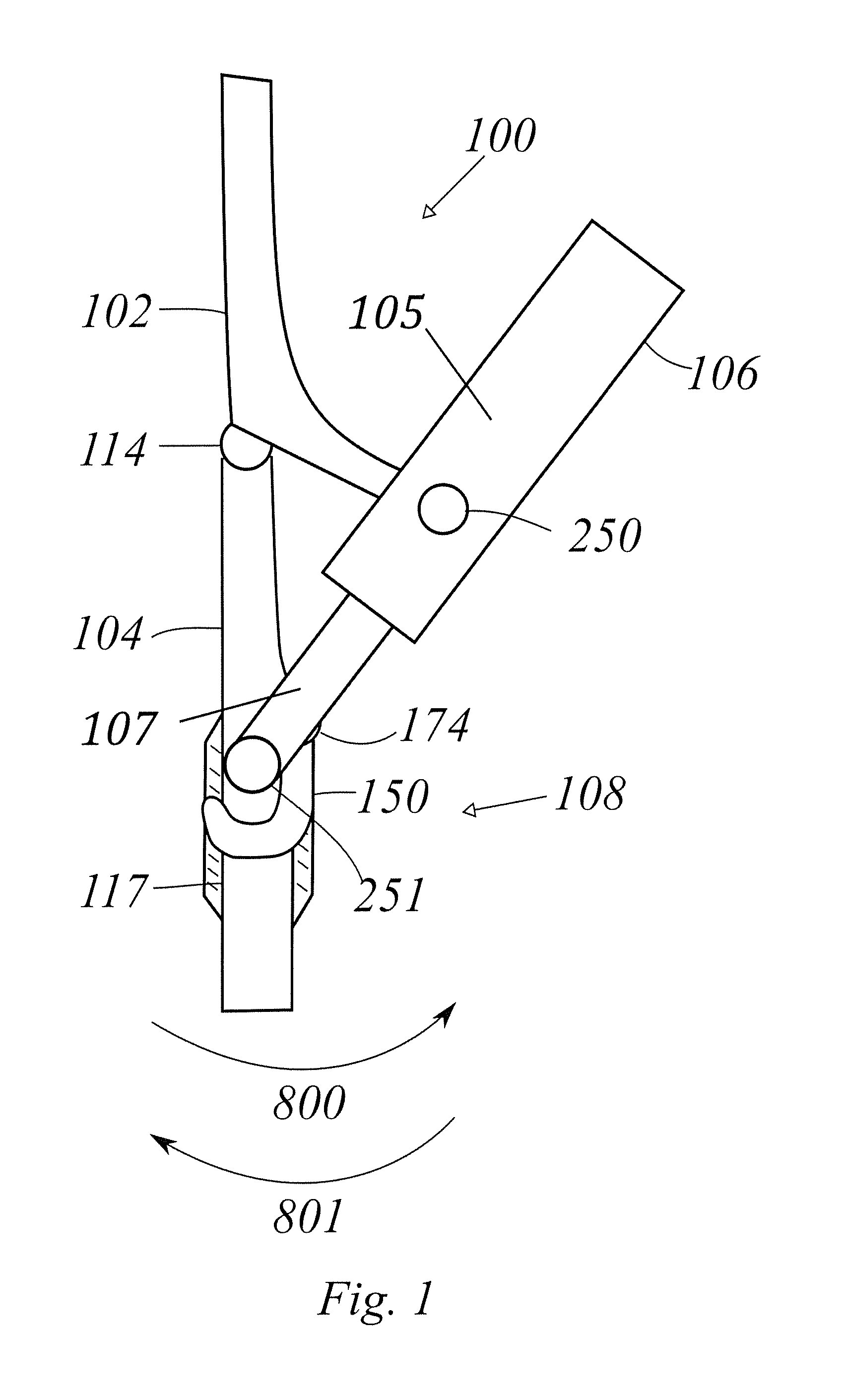
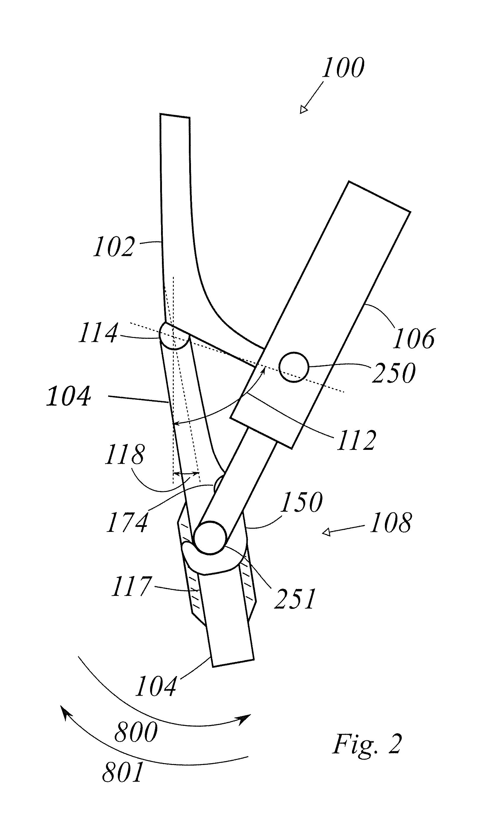
[0051]FIG. 1 shows an embodiment of a passive power-conservative artificial knee 100 which is configured to be coupled to a lower extremity of a person 200. FIG. 1 shows the passive power-conservative artificial knee 100 without a person 200 (depicted later in FIGS. 37-40). Passive power-conservative artificial knee 100, among other things, comprises a thigh link 102, a shank link 104, a compressive force generator 106, and a release mechanism 108. Shank link 104 is rotatably coupled to thigh link 102 along knee joint 114.

[0052]In some embodiments of the invention, as shown in FIG. 32, thigh link 102 is configured to move in unison with a user's thigh 202. In some embodiments of the invention, shank link 104 is configured to move in unison with a user's shank 204. In some embodiments of the invention, exoskeleton 100 further comprises a thigh connector 206 that allows coupling to a user's thigh 202, and a shank connector 208 that allows coupling to a user's shank 204. In some embodi...


PUM


Abstract

A passive artificial knee comprises first and second links rotatably coupled at a knee joint, a passive compressive force generator rotatably coupled to the second link, and a release mechanism coupled to the first link. When a relative angle of the first and second links is less than a toggle angle, the release mechanism locks in a first operational mode, and the force generator compresses, resisting the flexing of the second link relative to the first link. When the relative angle is larger than the toggle angle, the force generator decompresses and encourages the flexion of said second link relative to said first link. When the force generator is substantially extended and said compressive force is substantially small, the release mechanism moves into a second operational mode, wherein the force generator neither resists nor encourages the extension and flexion of said second link from said first link.

Description

FIELD OF THE INVENTION[0001]The present invention pertains to the art of artificial lower limb prosthetics and orthotic systems: more particularly, to a passive power-conservative artificial knee that can be used for a variety of orthotic applications.BACKGROUND ART[0002]A traditional knee-ankle-foot orthosis (KAFO) is used to increase the patient stability during the weight-bearing phase of walking. A traditional KAFO locks the knee in full extension, which provides stability. This locked posture results in patients' ability to ambulate with gait deviations that can lead to overuse injuries. A stance control orthosis (SCO) allows a user's knee to flex during a swing phase of a gait cycle, and prevents knee flexion for stability during the stance phase. By allowing the knee to bend during the swing phase, SCOs allow a more natural gait, which may reduce secondary complications from gait compensations and allow the user to walk with less effort.[0003]In general, stance control orthos...

Claims


Application Information

Patent Timeline
Patent Type & Authority Applications(United States)
IPC IPC(8): A61H3/00A61H1/02A61F2/68A61F5/01A61F2/64
CPCA61H3/00A61F5/0123A61F5/0127A61F2/64A61F2/68A61H1/0262A61H2201/1642A61F2005/0155A61F2002/6854A61F2002/5072A61H2201/165A61H2201/163A61F2005/0158A61H1/024A61H1/0244A61H2201/1207A61H2201/1246A61H2201/149A61H2201/1628A61H2201/164A61H2201/1676A61H2003/007
Inventor WU, SHANG-LIKAZEROONI, HOMAYOON
Owner RGT UNIV OF CALIFORNIA
Why Eureka
Try Eureka