Brightness calibration method and optical detection system

Active Publication Date: 2016-12-29
GLOBAL UNICHIP CORPORATION +1
View PDF4 Cites 1 Cited by
  • Summary
  • Abstract
  • Description
  • Claims
  • Application Information

AI Technical Summary

Benefits of technology

[0017]Accordingly, the brightness calibration method of the disclosure is substantially performed to dispose the diffusers having larger transparencies over the detection sites corresponding to smaller brightness values, and dispose the diffusers having smaller transparencies over the detection sites corresponding to larger brightness values. In other words, the brightness calibration method of the disclosure provides a rule to scre

Problems solved by technology

Single source illuminators in conventional optical detection systems usually have problems of uniformity.
In addition to the uniformity of the light source and the deviations of th

Method used


Image

  • Brightness calibration method and optical detection system
  • Brightness calibration method and optical detection system
  • Brightness calibration method and optical detection system

Examples


Example

[0027]Reference will now be made in detail to the present embodiments of the disclosure, examples of which are illustrated in the accompanying drawings. Wherever possible, the same reference numbers are used in the drawings and the description to refer to the same or like parts.

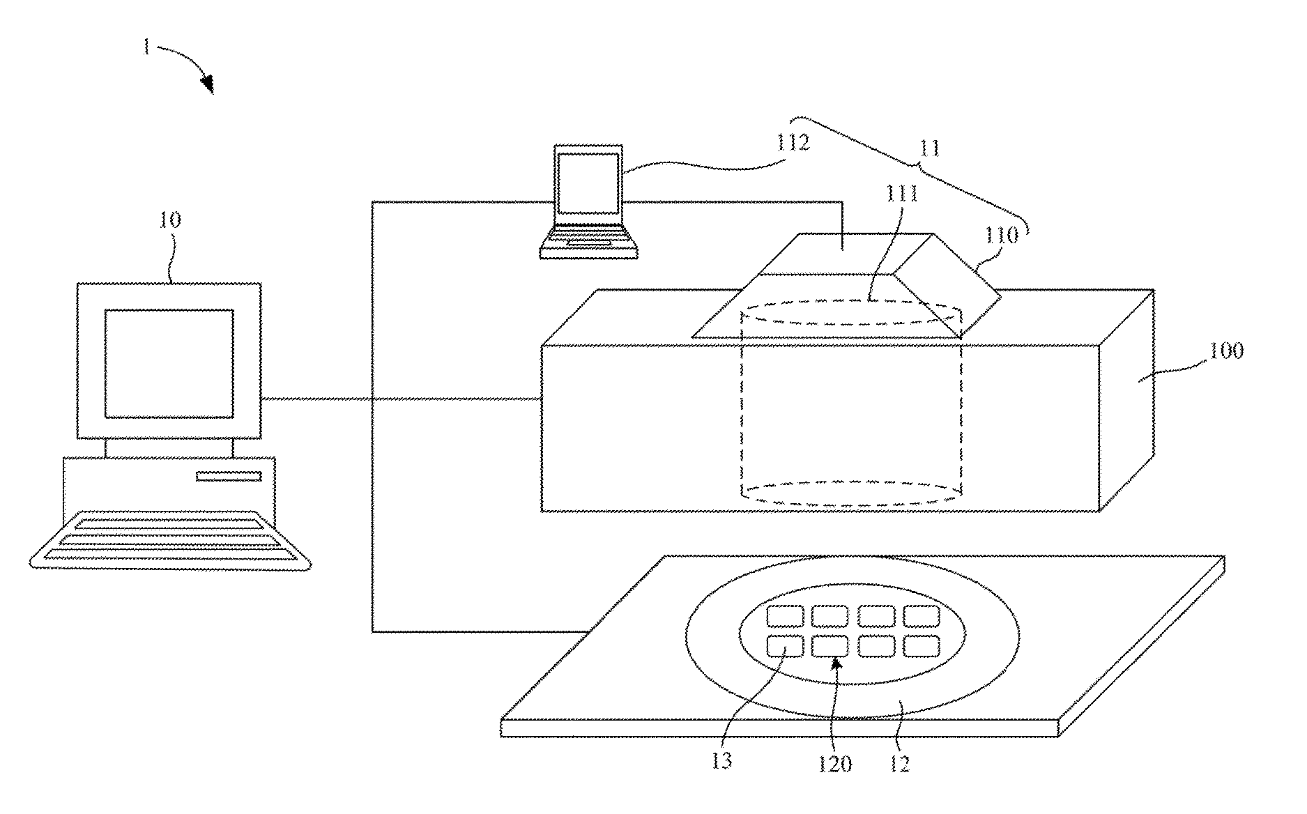
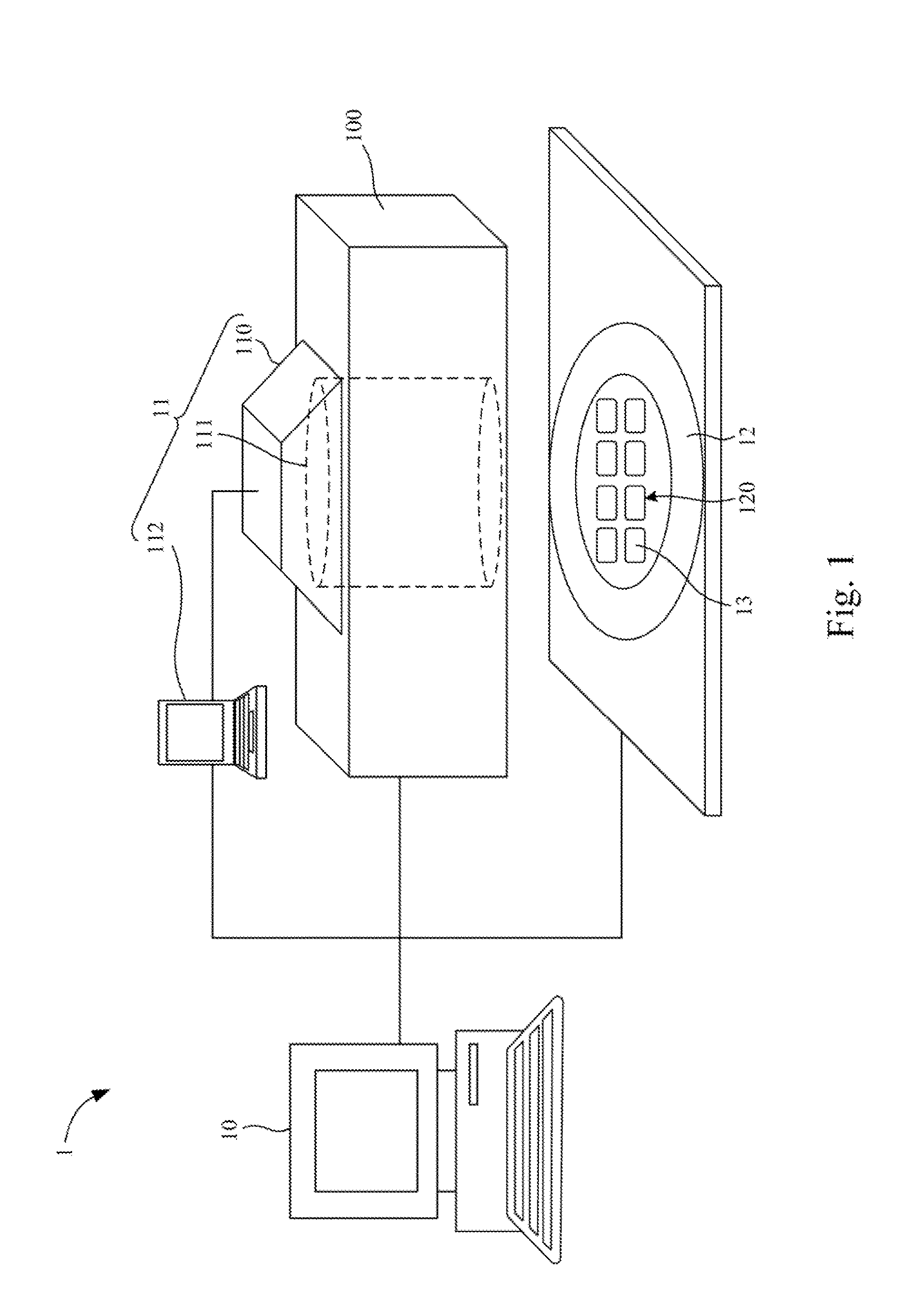
[0028]FIG. 1 is a top view of an optical detection system 1 according to an embodiment of the disclosure.

[0029]As shown in FIG. 1, in the embodiment, the optical detection system 1 includes a tester host 10, a tester head 100, a single source illuminator 11, a probe card 12, and a plurality of diffusers 13. The probe card 12 has a plurality of detection sites 120, and the diffusers 13 are respectively disposed over the detection sites 120 (i.e., respectively located under the diffusers 13). Each of the detection sites 120 is electrically connected to a sensing chip (not shown), so as to detect electrical or optical properties of the sensing chip. Owing to the uniformity of processes or the deviations among ba...


PUM


Abstract

A brightness calibration method used in an optical detection system includes a single source illuminator and a probe card. The single source illuminator is configured to illuminate the probe card. The probe card has a plurality of detection sites. The brightness calibration method includes: sequentially detecting brightness values at the detection sites through one of a plurality of diffusers by a sensing chip; sequentially detecting transparencies of the diffusers at one of the detection sites by the sensing chip; and selecting and respectively disposing the diffusers corresponding to larger ones of the transparencies over the detection sites corresponding to smaller ones of the brightness values, and selecting and respectively disposing the diffusers corresponding to smaller ones of the transparencies over the detection sites corresponding to larger ones of the brightness values.

Description

RELATED APPLICATIONS[0001]This application claims priority to Taiwan Application Serial Number 104120768 filed Jun. 26, 2015, which is herein incorporated by reference.BACKGROUND[0002]Technical Field[0003]The present disclosure relates to a brightness calibration method and an optical detection system.[0004]Description of Related Art[0005]Single source illuminators in conventional optical detection systems usually have problems of uniformity. In a normal way, the intensity at the central region of the light illuminated from a single source illuminator is greater than that at the peripheral region of the light. If a multi-DUT probe card used in a conventional optical detection system, brightness values of light received by the respective detection sites of the probe card might differ from each other. In order to solve such problem, the conventional optical detection system is further equipped with diffusers disposed over the detection sites, so as to homogenize the light.[0006]On the...

Claims


Application Information

Patent Timeline
IPC IPC(8): G01J1/02G01J1/42G01J1/44G01J1/04
CPCG01J1/0295G01J1/0448G01J2001/444G01J1/4228G01J1/44G01J1/0474G01J1/0418G01J1/08G01J2001/083G01J2001/4247G01N2201/0634
Inventor LIU, CHANG-MINGLO, PI-TSANHSU, SHIH-HUALIN, CHIEN-HAOLEE, TENG-HUIHSIEH, TSUNG-JU
Owner GLOBAL UNICHIP CORPORATION
Why Eureka
Try Eureka