
Organic light emitting display device

a display device and organic technology, applied in the direction of solid-state devices, semiconductor devices, thermoelectric devices, etc., can solve the problems of unnecessarily emitting lights by pixels adjacent to the non-pixel area, deteriorating display quality, and current leakage through the plurality of organic layers disposed in the non-pixel area, so as to reduce or minimize the amount of leakage current, reduce color mixing between pixels, and reduce current leakage

Active Publication Date: 2016-12-29
LG DISPLAY CO LTD
View PDF5 Cites 25 Cited by
  • Summary
  • Abstract
  • Description
  • Claims
  • Application Information

AI Technical Summary

Benefits of technology

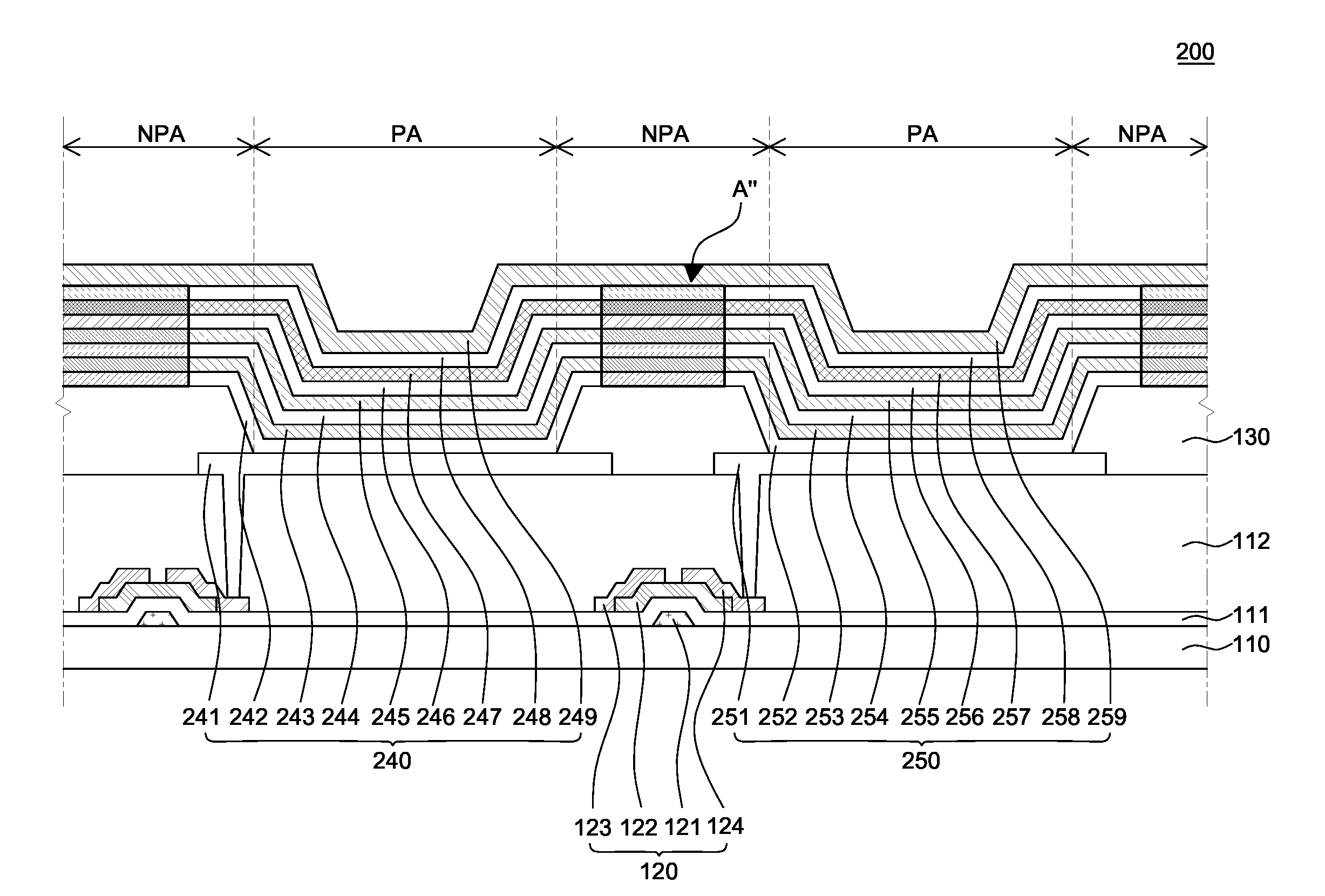
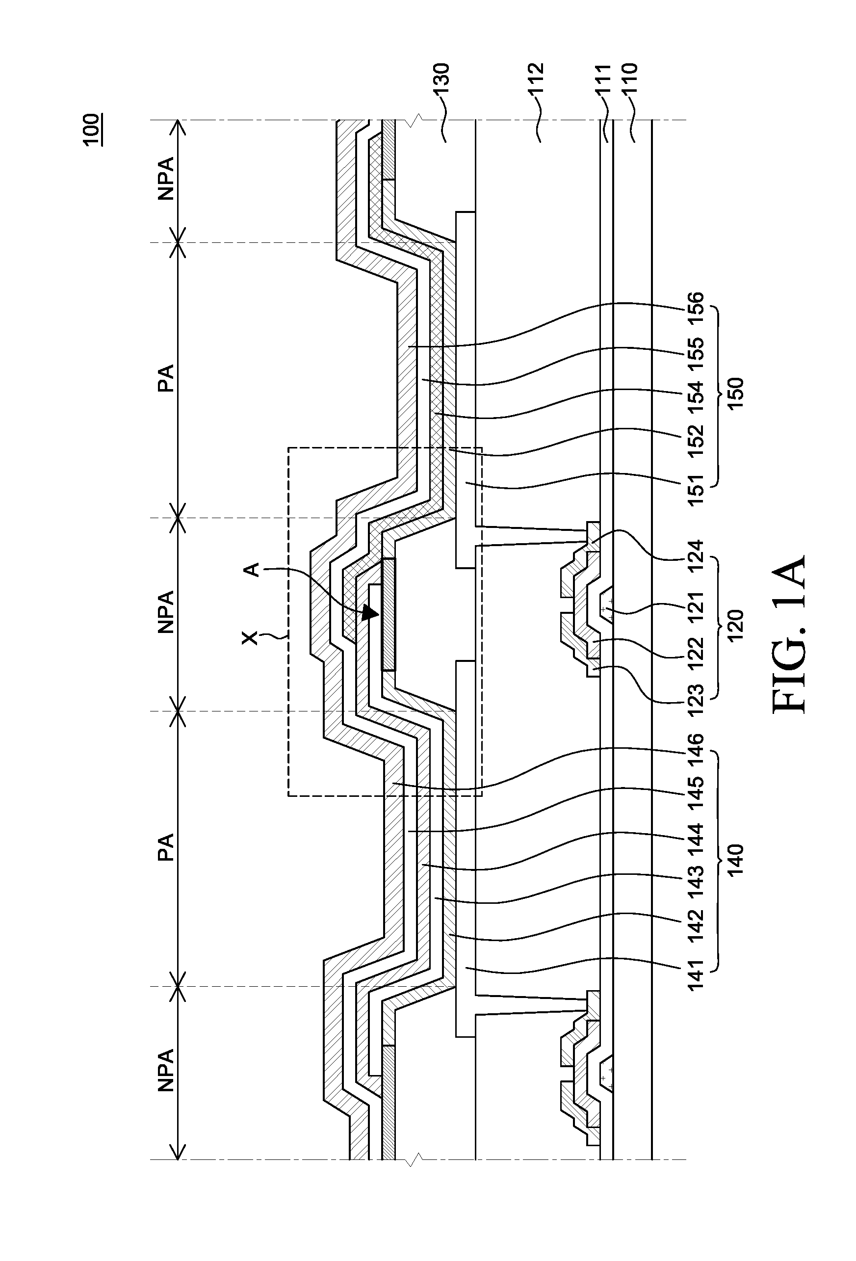
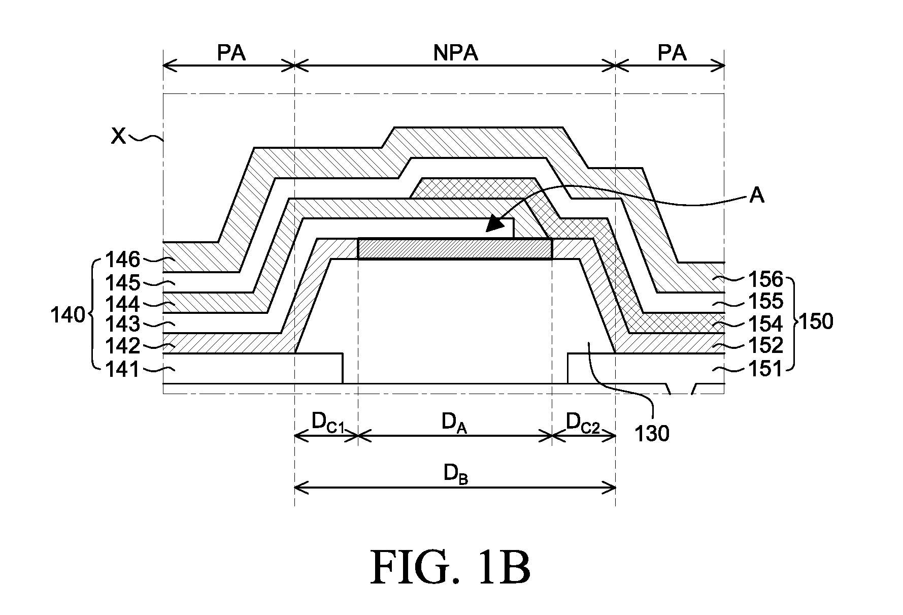
The patent aims to improve the display quality of OLED devices by reducing current leaking and color mixing between pixels. This is achieved by designing a common layer that includes a characteristic degradation area, which helps to minimize these issues. Overall, the technical effect of this patent is to enhance the performance and image quality of OLED devices.

Problems solved by technology

In the OLED device, a display quality may deteriorate due to a current leaking to an unintended area, i.e., an area where a light should not emitted.
In this case, when the OLED device is driven, a current may leak through the plurality of organic layers disposed in the non-pixel area.
Thus, in addition to a pixel being driven, pixels adjacent thereto may unnecessarily emit lights.
Therefore, a light may be unnecessarily emitted from an undesired pixel or area, which may cause color mixing between pixels and thus deteriorate a display quality.
In this case, when the OLED device is driven, a current may leak through the organic layers disposed in a non-pixel area.
Thus, pixels adjacent to a pixel being driven may unnecessarily emit lights.
Further, when organic light emitting layers are deposited in each pixel using the FMM, the organic light emitting layers may be unnecessarily formed in a portion of the non-pixel area due to a mask alignment error.
This may cause color mixing between pixels and thus deteriorate a display quality.

Method used


Image

  • Organic light emitting display device
  • Organic light emitting display device
  • Organic light emitting display device

Examples


Embodiment Construction

[0032]Advantages and features of the present disclosure, and methods for accomplishing the same will be more clearly understood from exemplary embodiments described below with reference to the accompanying drawings. However, the present disclosure is not limited to the following exemplary embodiments but may be implemented in various different forms. The exemplary embodiments are provided only to complete disclosure of the present disclosure and to fully provide a person having ordinary skill in the art to which the present disclosure pertains with the category of the disclosure, and the present disclosure will be defined by the appended claims.

[0033]The shapes, sizes, ratios, angles, numbers, and the like shown in the accompanying drawings for describing the exemplary embodiments of the present disclosure are merely examples, and the present disclosure is not limited thereto. Like reference numerals generally denote like elements throughout the present specification. Further, in th...


PUM


Abstract

Provided is an organic light emitting display device including at least two organic light emitting elements disposed adjacent to each other, respectively including an anode, an organic light emitting unit, and a cathode, and sharing at least one common layer in the organic light emitting unit. The at least one common layer includes a characteristic degradation area that reduces or minimizes an amount of leakage current generated between the at least two organic light emitting elements.

Description

CROSS-REFERENCE TO RELATED APPLICATIONS[0001]This application claims the priority of Korean Patent Application No. 10-2015-0090586 filed on Jun. 25, 2015, in the Korean Intellectual Property Office, the disclosure of which is incorporated by reference for all purposes as if fully set forth herein.BACKGROUND[0002]Field[0003]The present disclosure relates to an organic light emitting display device and a method of manufacturing the same. More particularly, the present disclosure relates to an organic light emitting display device in which an amount of leakage current generated between pixels can be reduced or minimized.[0004]Description of the Related Art[0005]An organic light emitting display (OLED) device is a next-generation display device having a self-luminance characteristic. The OLED device includes an organic light emitting element including two electrodes and an organic light emitting layer disposed between the two electrodes. The organic light emitting element uses the princ...

Claims


Application Information

Patent Timeline
Patent Type & Authority Applications(United States)
IPC IPC(8): H01L27/32H01L51/50
CPCH01L27/3246H01L51/5088H01L51/5056H01L27/3262H10K50/17H10K59/122H10K50/15
Inventor CHO, JUNGMOSEOK, HANBYEOLLEE, SOHEE
Owner LG DISPLAY CO LTD
Learn More