Handheld camera stabilizer with integration of smart device

a smart device and stabilizer technology, applied in the field of hand-held stabilizers, can solve the problems of unusable arrangement, inability to stabilize the roll, and no integration between the stabilizer and the camera devi

Inactive Publication Date: 2016-12-29
DELTRON INTELLIGENCE TECH LTD
View PDF1 Cites 97 Cited by
  • Summary
  • Abstract
  • Description
  • Claims
  • Application Information

AI Technical Summary

Benefits of technology

[0022]The controller may be further configured to wirelessly receive the target attitude from the camera device by using Bluetooth technology, WiFi or NFC. The stabilizer may further comprise an on-board control interface for receiving the target attitude manually from a user. The on-board control interface may be a joystick or a revolving rheostat.

Problems solved by technology

However, there are three rotary axes in the camera device, so that the roll attitude cannot be stabilized by the stabilization system disclosed in U.S. Pat. No. 7,642,741.
In addition, no integration is built between the stabilizer and the camera device.
This arrangement is not user-friendly.
This stabilization mechanism has a large torque but results in a long response time.
Hence, the resultant stabilization effect may be not good.
In addition, the configuration of this stabilization mechanism can only provide attitude stabilization about two axes: the roll attitude and the pitch attitude.
It is observed that, insofar as the Inventors are aware of, there is a lacking of a stabilizer that can provide fast response stabilization for a camera device for three rotary axes (pitch, roll and yaw) as well as that is integrated with the camera device.

Method used


Image

  • Handheld camera stabilizer with integration of smart device
  • Handheld camera stabilizer with integration of smart device
  • Handheld camera stabilizer with integration of smart device

Examples


first embodiment

A. First Embodiment of the Stabilizer

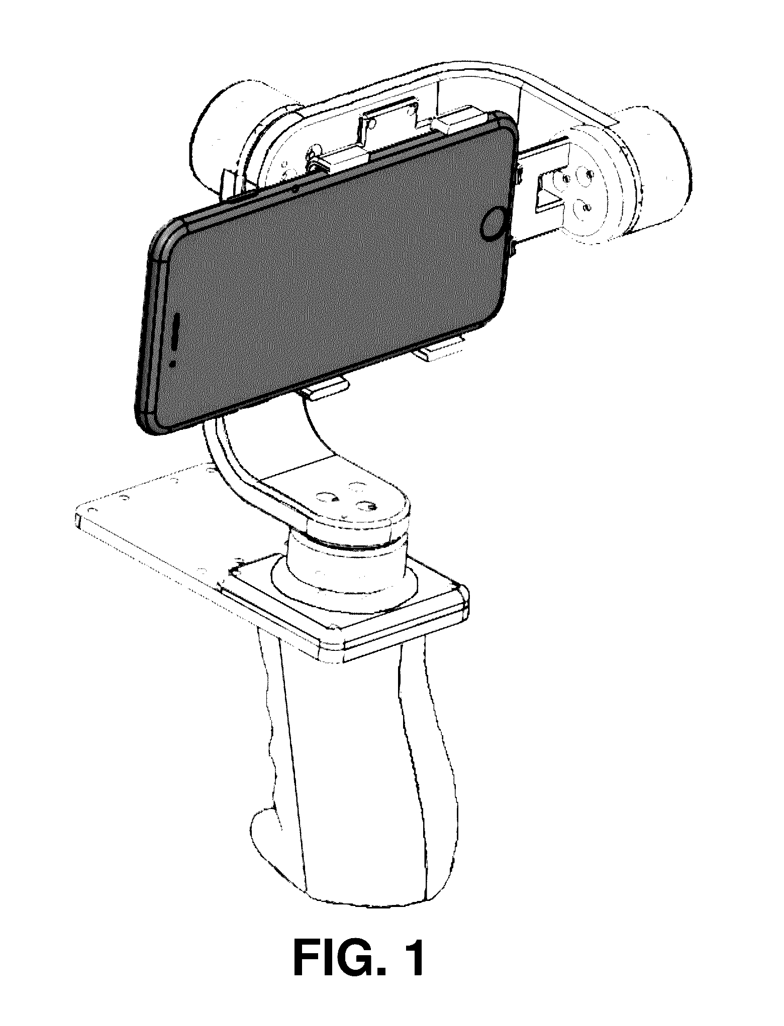
[0046]FIG. 1 depicts a perspective view of a first embodiment of the disclosed handheld stabilizer holding an iPhone 6 as an illustration of the operation of the first embodiment.

A.1. Structure

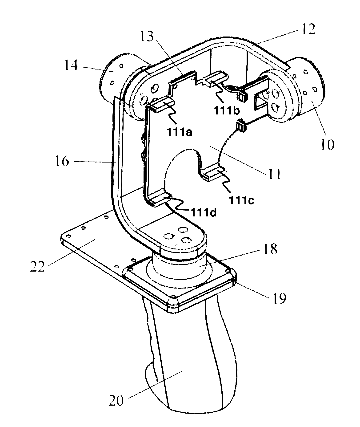
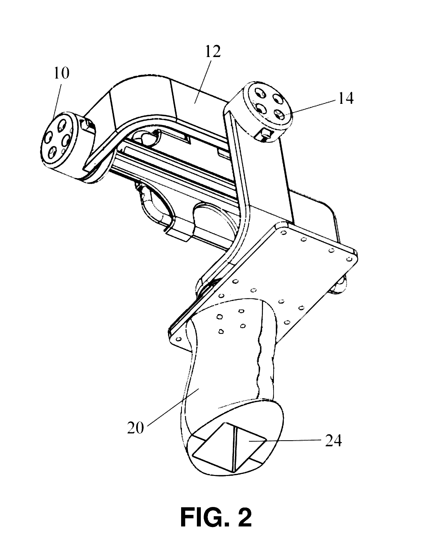
[0047]FIG. 3 is a perspective view of the first embodiment of the stabilizer. A camera device mount 11 is a mechanism for holding the camera device (e.g. a sport camera like Gopro and a smartphone with photo- and video-taking functionality such as an iPhone). Typically, the holding mechanism can be implemented with 4 fixed holders 111a-d to hold the camera device. However, the holding mechanism can also have a different mechanism to hold the camera device, such as a width-adjustable mounting mechanism and any mechanism of different shape, different size and materials. The stabilizer includes an IMU sensor 13. In one option, the IMU sensor 13 is joined to the camera device mount 11. Thus, the IMU sensor 13 can faithfully measure the attitude of the camera de...

second embodiment

B. Second Embodiment of the Stabilizer

B.1. Structure

[0063]FIG. 13 is a perspective view of a second embodiment of the disclosed stabilizer. The whole second embodiment of the stabilizer comprises similar components of the stabilizer set forth in the first embodiment. A camera device mount 11′ holds an iPhone 4S as the camera device and is joined to a motor A 10′. It is possible to attach an IMU sensor 13′ to the camera device mount 11′ by screws. However, other methods of attaching the IMU sensor 13′ are also suitable, for example, using glue. A connection bar A 14′ is joined to the motor A 10′ and a motor B 12′. A connection bar B 16′ is joined to the motor B 12′ and a motor C 18′. The motor C 18′ is joined to a handle 20′. A space for a circuit board 22′ is a space for housing a controller circuit board. A battery container 24′ is a storage space for one or more batteries.

[0064]FIG. 12 illustrates the definition of two shooting modes (portrait shooting mode and landscape shooting ...

third embodiment

C. Third Embodiment of the Stabilizer

C.1. Structure

[0069]FIG. 16 is a perspective view of a third embodiment of the stabilizer viewed from above. The whole third embodiment comprises similar components of the stabilizer set forth in the first embodiment. A camera device mount 11″ holds an iPhone 6 as the camera device and is joined to a motor A 10′. It is possible to attach an IMU sensor 13″ to the camera device mount 11″ by screws. However, other methods of attachment are also suitable, for example, using glue. A connection bar A 14″ is joined to the motor A 10″ and the motor B 12″. A connection bar B 16″ is joined to the motor B 12″ and the motor C 18″. The motor C 18″ is joined to a handle 20″. A space for circuit board 22″ is a space to allocate a controller circuit board. The controller circuit board attached on the handle 20″ has an additional IMU sensor so that the controller can measure the attitude of the handle 20″. A battery container 24″ (See FIG. 15) is a storage space ...


PUM


Abstract

A handheld stabilizer for automatically stabilizing a camera device, such as a smartphone, when the camera device is mounted on the stabilizer is provided. The stabilizer comprises a camera device mount for holding the camera device, a plurality of motors collectively arranged to cause the camera device mount to be rotatable about three predetermined substantially-orthogonal axes, an inertial-measurement unit (IMU) sensor for measuring an angle and an angular velocity experienced by the camera device about each of the three axes, and a controller. By means of the IMU sensor, an attitude of the camera device is measured. The controller is configured to estimate an attitude error of the camera device according to the measured attitude, and to automatically control the plurality of motors in response to the attitude error so as to controllably rotate the camera device about each of the three axes to counter the attitude error.

Description

CROSS-REFERENCE TO RELATED APPLICATION[0001]This application claims the benefit of U.S. Provisional Application No. 62 / 184,265, filed 25 Jun. 2015, the disclosure of which is incorporated by reference herein in its entirety.LIST OF ABBREVIATIONS AND TECHNICAL TERMS WITH EXPLANATION[0002]3D Three-dimensional.[0003]ADC Analog-to-digital converter: a device helping a MCU to read a voltage value.[0004]BLDC motor Brushless direct-current motor: a motor that can provide fast response and a torque to stabilize an attitude of a camera device.[0005]DMP Digital motion processor: a processor having a function, provided by the IMU manufacturer, InvenSense, which fuses data from an IMU sensor to get an accurate attitude.[0006]IC Integrated circuit.[0007]IMU Inertial-measurement unit: a sensor that can measure a rotation rate and a direction of gravity, thereby outputting attitude information.[0008]MCU Micro-controller unit: a programmable controller such as STM32 from STMicroelectronics.[0009]ME...

Claims


Application Information

Patent Timeline
Patent Type & Authority Applications(United States)
IPC IPC(8): H04N5/232H04N5/225
CPCH04N5/2328H04N5/23203H04N5/23258H04N5/2253F16M11/041F16M11/10F16M11/18F16M11/2071F16M13/04H04N23/50H04N23/66H04N23/698H04N23/6812F16M13/00H04N23/685
Inventor CHENG, XURANZENG, CANCHENG
Owner DELTRON INTELLIGENCE TECH LTD
Why Eureka
Try Eureka