Method of injection molding with constant-velocity flow front control

a flow front and constant-speed technology, applied in the field of injection molding parts, can solve the problems of constricting the flow path, adversely affecting the non-newtonian properties of molten thermoplastic materials, other optical discontinuities in molded parts, etc., and achieve the effect of decreasing the flow front velocity and increasing the cycle tim

Inactive Publication Date: 2017-01-05
IMFLUX INC
View PDF5 Cites 29 Cited by
  • Summary
  • Abstract
  • Description
  • Claims
  • Application Information

AI Technical Summary

Problems solved by technology

These sudden variations in flow front velocity adversely affect the non-Newtonian properties of the molten thermoplastic material.
The flow front velocity variations can lead to striations or flow lines or cause other optical discontinuities in the molded parts.
The non-uniformity in flow front velocity can also lead to localized areas within the mold cavity where thermoplastic material freezes off prematurely, potentially constricting the flow path for further molten thermoplastic material to fill the rest of the part, and dramatically decreasing flow front velocity.
Short shots are also commonly attributed to flow restrictions caused by such thickness changes.
In addition to adverse aesthetic effects, this can adversely impact the part's structural integrity and drastically increase cycle times. It would be desirable if mold modeling software could be used to determine a set of operating conditions for the ram or screw of an injection molding system that maintains constant velocity of the flow front from beginning-of-fill to end-of-fill, despite changes in cross-sectional area of the mold cavity.

Method used


Image

  • Method of injection molding with constant-velocity flow front control
  • Method of injection molding with constant-velocity flow front control
  • Method of injection molding with constant-velocity flow front control

Examples


Embodiment Construction

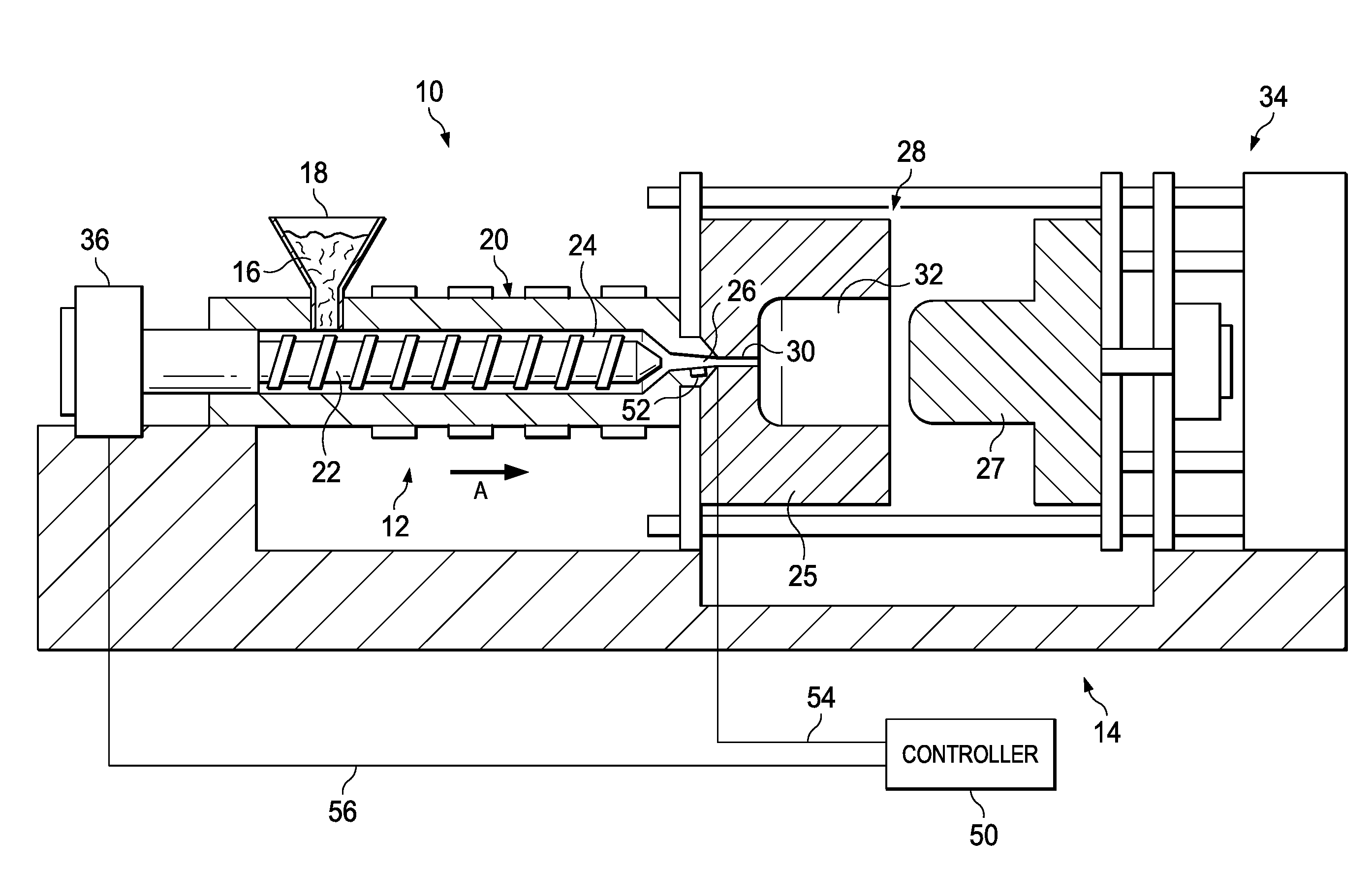
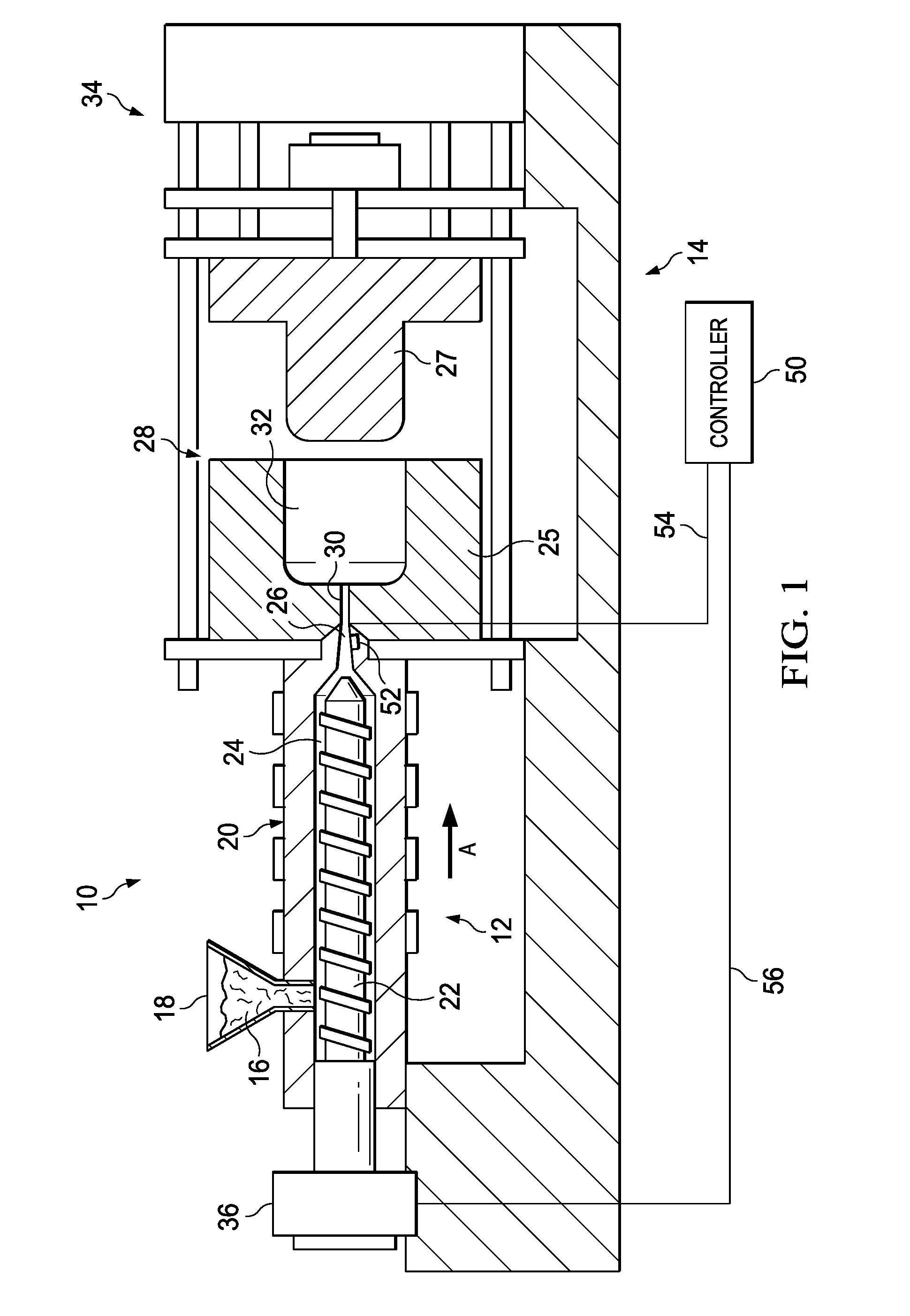
[0019]Referring to the figures in detail, FIG. 1 illustrates an exemplary injection molding apparatus 10 for producing thermoplastic parts in high volumes (e.g., a class 101 or 30 injection mold, or an “ultra-high productivity mold”), especially thinwalled parts having an L / T ratio of 100 or greater. The injection molding apparatus 10 generally includes an injection system 12 and a clamping system 14. A thermoplastic material may be introduced to the injection system 12 in the form of thermoplastic pellets 16. The thermoplastic pellets 16 may be placed into a hopper 18, which feeds the thermoplastic pellets 16 into a heated barrel 20 of the injection system 12. The thermoplastic pellets 16, after being fed into the heated barrel 20, may be driven to the end of the heated barrel 20 by a ram, such as a reciprocating screw 22. The heating of the heated barrel 20 and the compression of the thermoplastic pellets 16 by the reciprocating screw 22 causes the thermoplastic pellets 16 to melt...


PUM

PropertyMeasurementUnit
pressureaaaaaaaaaa
pressureaaaaaaaaaa
temperatureaaaaaaaaaa

Abstract

In order to injection mold parts at a constant flow front velocity in a mold cavity of an injection molding system, particularly where the mold cavity has a varying thickness along its length, mold modeling software is used to calculate the cross-sectional area as a function of the distance from the gate, percentage of fill, or length of the mold cavity. Based on that cross-sectional area, the mold modeling software determines an appropriate recommended ram force profile and / or melt pressure profile that would result in filling the mold cavity at a constant flow rate. An injection molding system is then operated according to the recommended ram force profile and / or melt pressure profile.

Description

FIELD OF THE INVENTION[0001]This application relates generally to injection molding and, more specifically, to methods for injection molding parts, especially variable-thickness parts, by maintaining a constant flow rate within the mold cavity during the injection molding process.BACKGROUND OF THE INVENTION[0002]A useful resource for injection molders is mold modeling software. Mold modeling software can provide output in the form of graphical images of a simulated molded part or portion thereof with, for example, contour lines depicting the progression of one or more flow fronts. Such graphical images can include thermal images to illustrate temperature gradients across and along a part. Output of mold modeling simulations is useful for predicting (and thereby enabling redesign or optimization of a mold or molding component so as to reduce) locations of increased or peak stress, part defects, including short-shots, warpage, excess flashing, flow lines, and sink marks. The output ca...

Claims


Application Information

Patent Timeline
Patent Type & Authority Applications(United States)
IPC IPC(8): B29C45/77B29C45/78B29C45/76B29C45/80
CPCB29C45/77B29C45/80B29C45/78B29C45/7646B29C2945/76006B29K2101/12B29C2945/76287B29C2945/76538B29C2945/76531B29C2945/76498B29C2945/76545B29C2945/7604B29C45/766B29C45/7693B29C2945/76013B29C2945/7618B29C2945/76381B29C2945/76859B29C2945/76936
Inventor HANSON, III, HERBERT KENNETHHUANG, CHOW-CHIALTONEN, GENE MICHAEL
Owner IMFLUX INC
Why Eureka
Try Eureka