Linear motion mechanism, governing valve drive device, and steam turbine
a technology of governing valve and drive device, which is applied in the direction of valve operating means/release devices, machines/engines, etc., can solve the problems of specific portion of the meshing portion of the ball screw, and achieve the effect of easy supply of grease, easy and reliable maintenance of the ball screw, and high reliability
- Summary
- Abstract
- Description
- Claims
- Application Information
AI Technical Summary
Benefits of technology
Problems solved by technology
Method used
Image
Examples
first embodiment
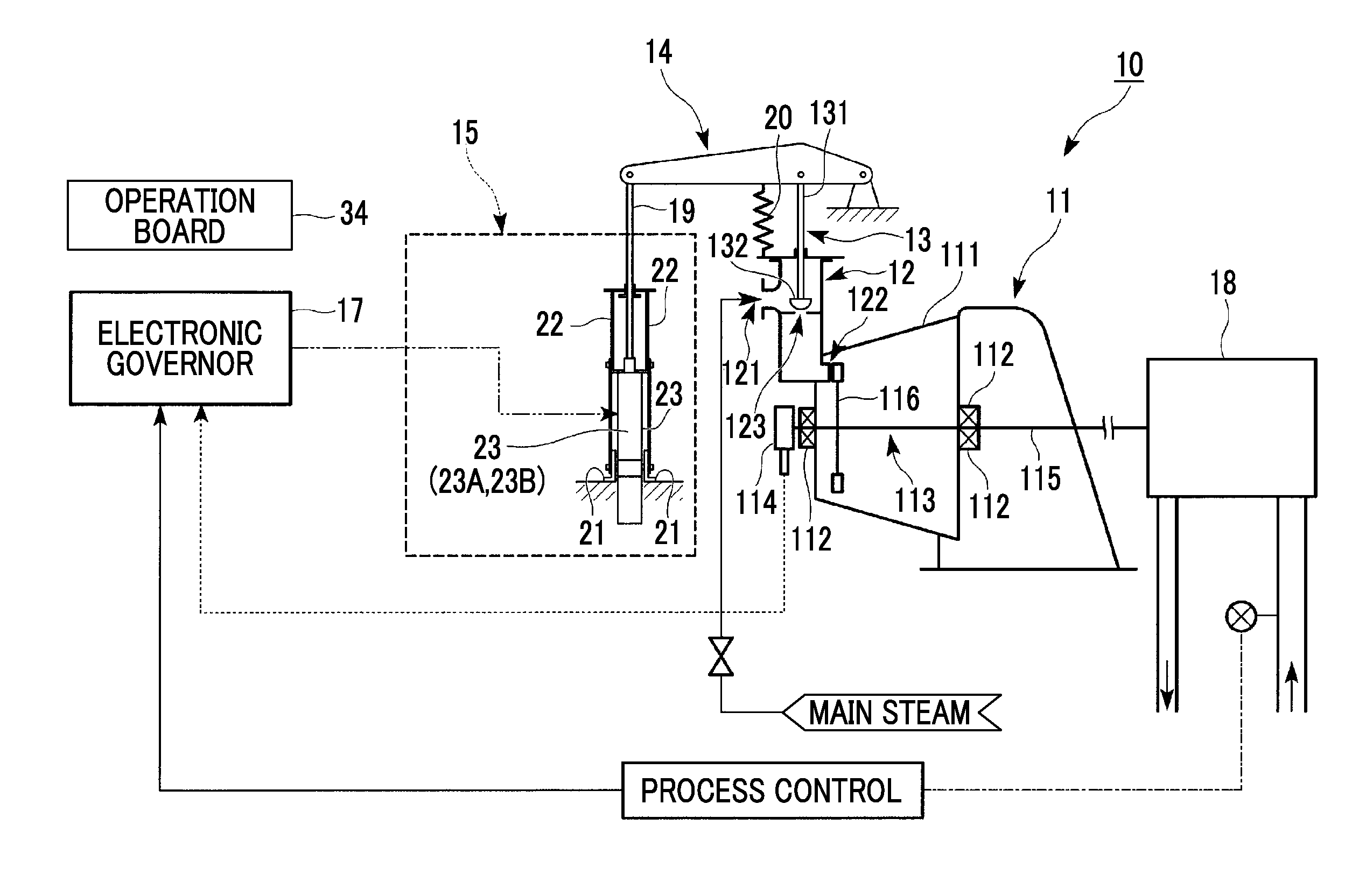
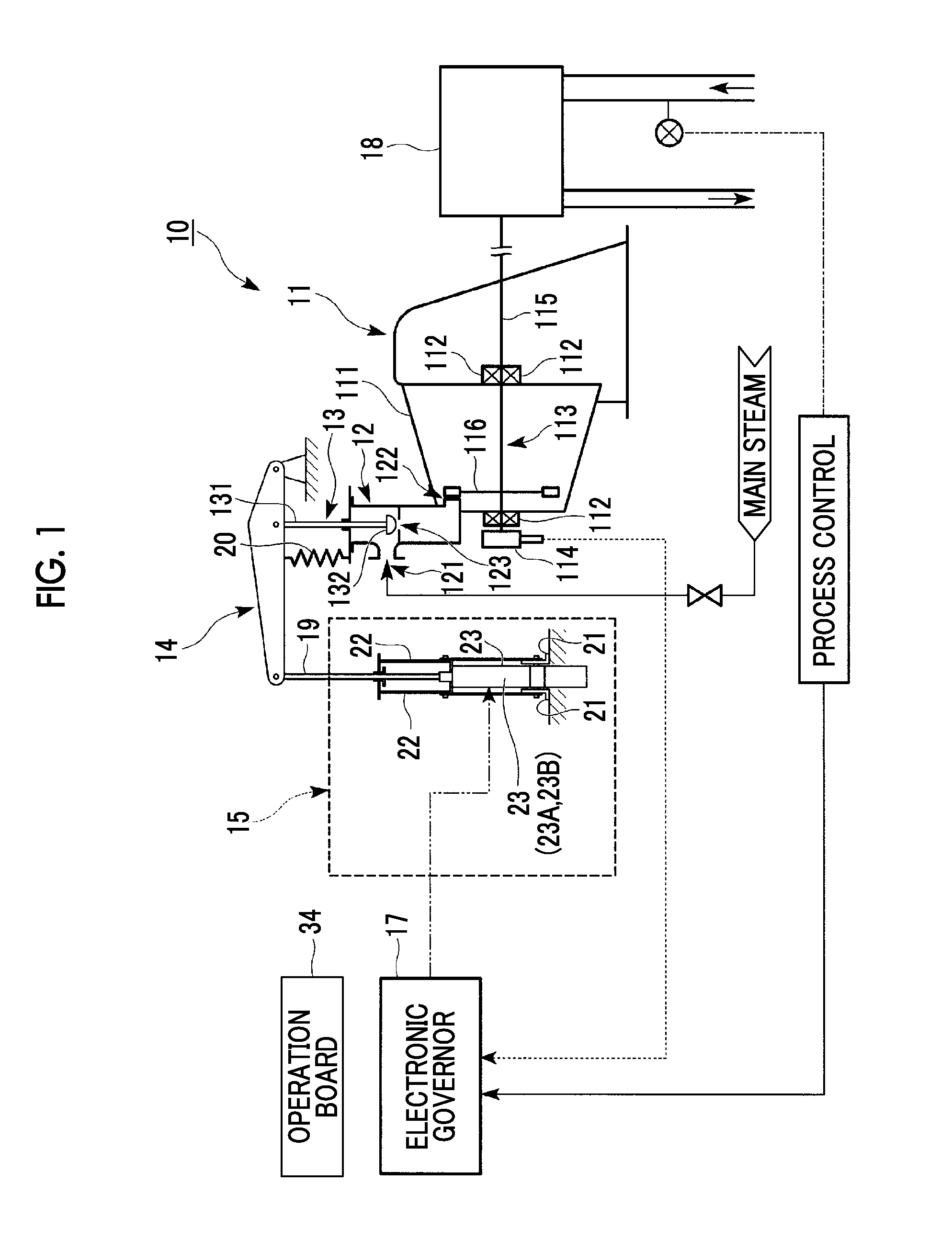
[0042]FIG. 1 is a schematic view showing the entire configuration of a steam turbine 10 according to an embodiment of the present invention.
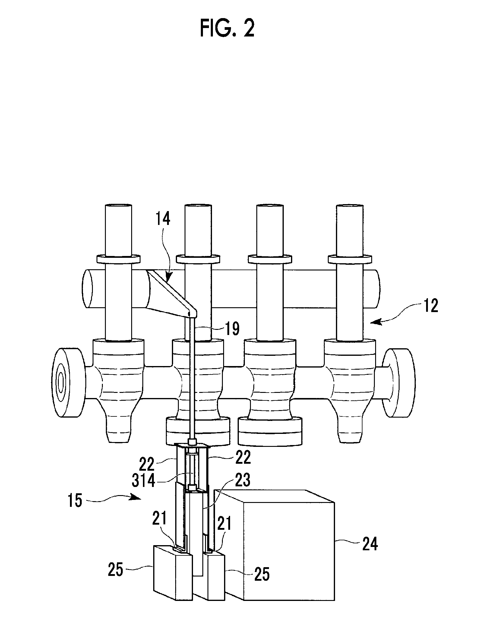
[0043]As shown in FIG. 1, the steam turbine 10 of the present embodiment includes a turbine main body 11, a steam channel 12 through which steam serving as a working fluid flows, a governing valve 13, a lever member 14, a governing valve drive device 15, and an electronic governor 17 which controls the governing valve drive device 15.
[0044]The turbine main body 11 includes a tubular casing 111, a bearing 112 which is provided in the casing 111, a rotor 113 which is rotatably supported by the bearing 112 and is disposed inside the casing 111, and a speed detection sensor 114 which detects a rotating speed of the rotor 113. The rotor 113 includes a rotary shaft 115, and a plurality of blades 116 which are fixed to the rotary shaft 115.
[0045]The blades 116 configured as described above are rotated by steam, and a compressor 18 is driven by the rota...
second embodiment
[0086]Next, a second embodiment of the ball screw mechanism 27, the governing valve drive device 15, and the steam turbine 10 according to the present invention will be described. In the second embodiment described below, only the configuration of the grease supply mechanism in the ball screw mechanism 27 is different from that of the first embodiment. Accordingly, the same reference numerals are assigned to the same portions as those of the first embodiment, and overlapping descriptions thereof are omitted.
[0087]FIG. 6 is an enlarged main sectional view showing the configuration of the grease supply mechanism of the ball screw mechanism 27 of the steam turbine 10 in the second embodiment.
[0088]As shown in FIG. 6, similarly to the first embodiment, in the ball screw mechanism 27, as the grease supply mechanism, the nut-side grease supply hole 321 which is formed in the nut 311 and the cylinder rod-side grease supply hole 322 which is formed in the cylinder rod 312 are provided.
[0089...
third embodiment
[0093]Next, a third embodiment of the ball screw mechanism 27, the governing valve drive device 15, and the steam turbine 10 according to the present invention will be described. In the third embodiment described below, since only the configuration of the grease supply mechanism in the ball screw mechanism 27 is different from those of the first and second embodiments, the same reference numerals are assigned to the same portions, and overlapping descriptions thereof are omitted.
[0094]FIG. 7 is an enlarged main sectional view showing the configuration of the grease supply mechanism of the ball screw mechanism 27 of the steam turbine 10 in the third embodiment.
[0095]As shown in FIG. 7, similarly to the second embodiment, as the grease supply mechanism of the ball screw mechanism 27, the nut-side grease supply hole 321 which is formed in the nut 311 and the cylinder rod-side grease supply hole 322 which is formed in the cylinder rod 312 are provided.
[0096]In addition, in the ball scre...
PUM
 Abstract
Description
Claims
Application Information
 - R&D
- Intellectual Property
- Life Sciences
- Materials
- Tech Scout
- Unparalleled Data Quality
- Higher Quality Content
- 60% Fewer Hallucinations
Browse by: Latest US Patents, China's latest patents, Technical Efficacy Thesaurus, Application Domain, Technology Topic, Popular Technical Reports.
© 2025 PatSnap. All rights reserved.Legal|Privacy policy|Modern Slavery Act Transparency Statement|Sitemap|About US| Contact US: help@patsnap.com


