Operating clock synchronization adjusting method for induction type power supply system

a technology of induction type and synchronization, which is applied in the direction of power supply for data processing, instruments, generating/distributing signals, etc., can solve the problems of inability to conduct charging and data transmission synchronously and must be carried out separately, damage or failure of objects being charged, and the timing of transmitting data signals to be accurate, resisting noise

Active Publication Date: 2017-01-05
FU TONG TECH
View PDF0 Cites 0 Cited by
  • Summary
  • Abstract
  • Description
  • Claims
  • Application Information

AI Technical Summary

Benefits of technology

[0015]In order to solve the above problem, the present invention provides a synchronous data transmitting method, for an induction type power supply system, capable of automatically calibrating and synchronizing timers in a supplying-end and receiving end, resisting noise and allowing timings of transmitting data signal to be accurate.

Problems solved by technology

These portable electronic devices and products tend to become light, thin, short and small in design.
Besides, usually charging and data transmission cannot be conducted synchronously and must be carried out separately.
Since wireless power energy can cause dangers and heat tip metal objects on the same principle as an induction stove, it is also easy to cause damage or failure of objects that are being charged due to heating effect.
For existing induction type power supply systems, the most important technical problem is the ability to identify objects placed on the supplying-end coil.
Like a cooking induction stove, induction power can transmit enormous energy of electromagnetic waves, which may heat up metal objects and cause dangers if directed towards these objects.
It is difficult to transmit data stably through induction coils for supplying power, because main carrier waves are transmitted by high-power electricity and may be affected by interferences occurring during use of power systems.
However, adding wireless communication devices into the existing induction type power supply system will lead to increase of manufacturing cost for the system.
When induction type power coils are used to transmit data, one problem that should be noticed is how to transmit and receive data synchronously.
And the supplying-end module cannot transmit data codes if not supplying power energy, so there are still considerable limitations and inconveniences in use of the induction type power supply system.
However, this way of encoding may result in a problem that modulation load is kept switching on within a cycle time.
Besides, in the process of modulation, the electric currents that originally go to the receiving-end module for output will be shunted by Rcm, thus reducing the output capability at the receiving-end module.
Due to the conflict of the above conditions, when the power of induction type power supply system is increased, data modulation with resistor loads will not work anymore.
Since signal modulation loads need to absorb considerably large electric currents and it leads to the problem of power loss following power increases, making it impossible to use this method, some firms propose a new method of capacitive signal modulation.
The shortcoming of this method lies in that all three variables are so weak that several amplification circuits are needed for analysis, making the circuit cost increase significantly.
This can be seen as an overload reaction, and at this time, the power supply system will lose the capability to increase amplitudes through signal modulation to transmit data, which may lead to the system failure.
When the output power is increased, the amplitude needs to be increased to Point C or D, resulting in system failure.

Method used


Image

  • Operating clock synchronization adjusting method for induction type power supply system
  • Operating clock synchronization adjusting method for induction type power supply system
  • Operating clock synchronization adjusting method for induction type power supply system

Examples


Embodiment Construction

[0051]To achieve the aforesaid objects and functions as well as the techniques adopted in the present invention and its fabrication, examples of the preferred embodiment of the present invention are given below to illustrate its features and functions in detail by referring to the accompanying drawings.

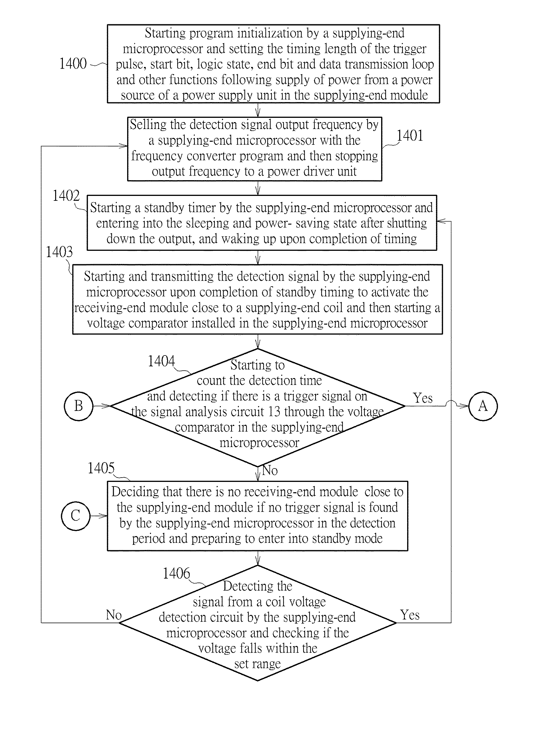
[0052]Referring to FIGS. 14A, 14B, 15-25, an induction type power supply system disclosed in the present invention includes a supplying-end module 1 and a receiving-end module 2. A method of transmitting power and data signals from said modules to a preset electronic device comprises the steps of:

[0053]Step 1400: Starting program initialization by a supplying-end microprocessor and setting the timing length of the trigger pulse, start bit, logic state, end bit and data transmission loop and other functions following supply of power from a power source 161 of a power supply unit 16 in the supplying-end module 1.

[0054]Step 1401: Selling the detection signal output frequency by a supplyi...


PUM


Abstract

A synchronous data transmitting method includes receiving, by a supplying-end module, a plurality of data impulses of power transmitting signal according to a first operating clock of a microprocessor in supplying-end module, for generating a plurality of data frames, wherein the plurality of data impulses is transmitted by receiving-end module according to a second operating clock of microprocessor in receiving-end module; calculating time periods between data impulses corresponding to start bits of the plurality of data frames, for acquiring a plurality of data frame periods; comparing the plurality of data frame periods with a data frame time period, for synchronizing the first operating clock and the second operating clock; and turning on a receiving function of the supplying-end module in a plurality of receiving periods and turning off the receiving function in a plurality of closed periods, wherein the plurality of receiving periods corresponds to the plurality of data impulses.

Description

CROSS REFERENCE TO RELATED APPLICATIONS[0001]This application is a Divisional of application Ser. No. 13 / 900,544 filed May. 23, 2013, which is a continuation-in-part application of U.S. patent applications Ser. No. 13 / 488,724 that was filed on Jun. 5, 2012 and is a continuation-in-part application of U.S. patent application Ser. No. 13 / 154,965 filed on Jun. 7, 2011.BACKGROUND OF THE INVENTION[0002]1. Field of the Invention[0003]The present invention relates to an operating clock synchronization adjusting method for an induction type power supply system. In the induction type power supply system with a method of time-synchronized data transmission, a supplying-end and a receiving-end of the induction type power supply system predict time of detecting data impulses via configuring timers of microprocessors and arranging operations of programs in the supplying-end and the receiving-end. In such a condition, the timers of the microprocessors in the supplying-end module and that of the m...

Claims


Application Information

Patent Timeline
Patent Type & Authority Applications(United States)
IPC IPC(8): G06F1/12H04B5/00G06F1/32
CPCH04B5/0031H04B5/0037H04B5/0075G06F1/12G06F1/324H02J50/10G06F1/3287
Inventor TSAI, MING-CHIUCHAN, CHI-CHE
Owner FU TONG TECH
Why Eureka
Try Eureka