
Cored Rock Analysis Planning Through CT Images

Active Publication Date: 2017-01-05
SAUDI ARABIAN OIL CO
View PDF2 Cites 7 Cited by
  • Summary
  • Abstract
  • Description
  • Claims
  • Application Information

AI Technical Summary

Benefits of technology

This patent describes a method and system for better planning and analyzing non-destructive core samples from subsurface materials. The system uses computerized tomography (CT) scanning images to create a virtual image of the state of the cores, which can be integrated into the planning process. This integrated image allows for better virtual marking of sample locations and better decision-making. The system can also simulate the positions of planned testing samples and can use a special purpose simulator machine. By using this advanced technology, the speed and accuracy of core analysis planning can be improved, leading to better results and cost savings. Overall, this disclosed system can provide a non-invasive and non-destructive tool for core analysis planning.

Problems solved by technology

Core analysis planning, however, often may be prepared with only a limited amount of available information about the actual core samples.
Since the actual state of the cores may not yet be known when core analysis planning decisions are made, estimations of plug or whole core rock samples (that is, the type, quantity, and location of plugs or other test samples, for instance) may not be accurate and may result in confusing expectations.
For example, fractures and rubble sections in a core may restrict the type, quantity, and location of plugs or other test samples that may be taken from such a core.
Such fractures and rubble sections may not be identifiable until the core is taken out of its protective barrel, cleaned, and examined on a viewing table.
These limitations may produce an inaccurate estimation of the number of testing samples that may be taken.
This method may be quite a lengthy process and may require supporting techniques to enhance accuracy as well as speed in the decision-making stage.
Applicant has recognized that, in existing types of core analysis planning, the actual state of the cores may not yet be known and that this limited knowledge impairs the effectiveness of core analysis planning.

Method used


Image

  • Cored Rock Analysis Planning Through CT Images
  • Cored Rock Analysis Planning Through CT Images
  • Cored Rock Analysis Planning Through CT Images

Examples


Embodiment Construction

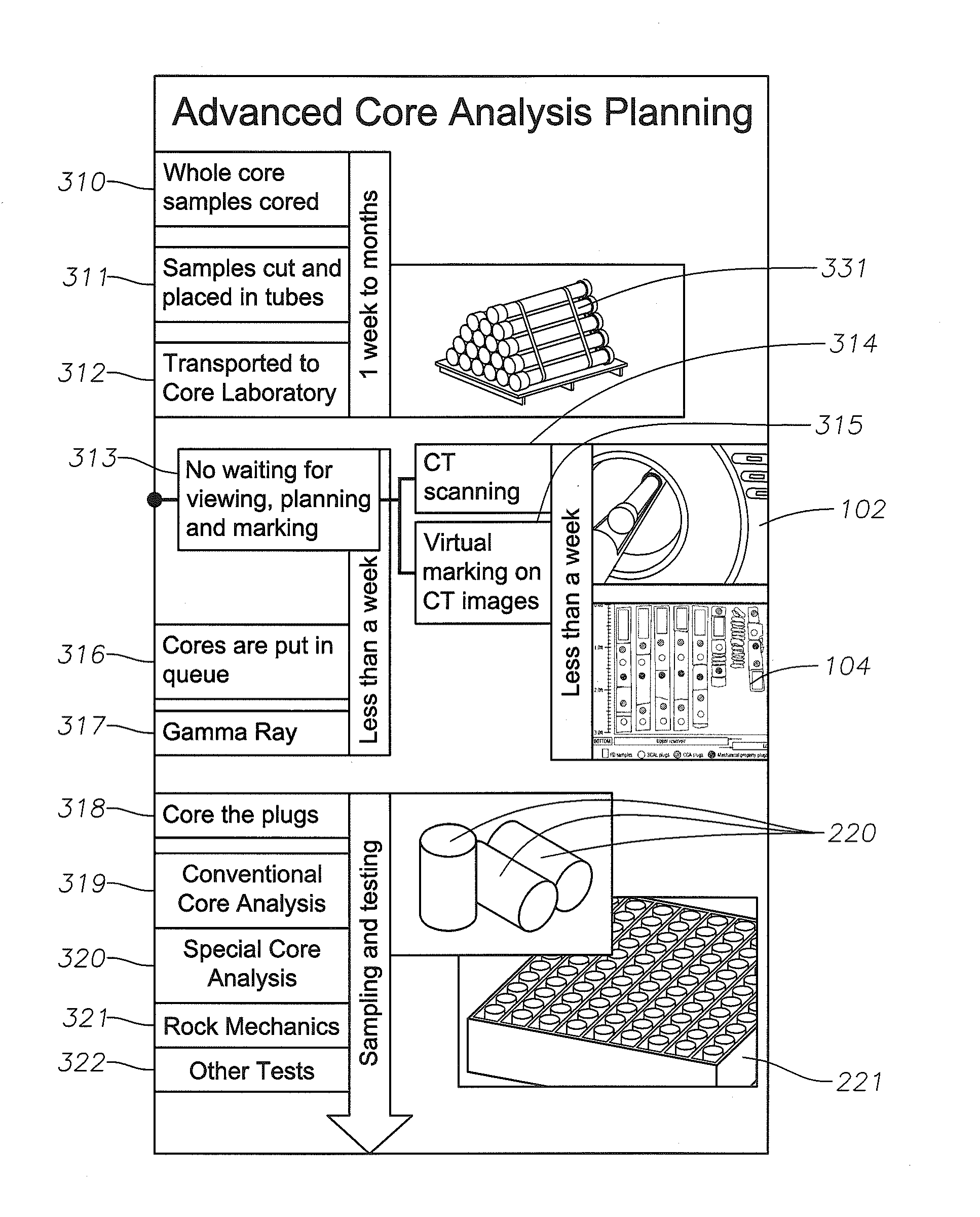
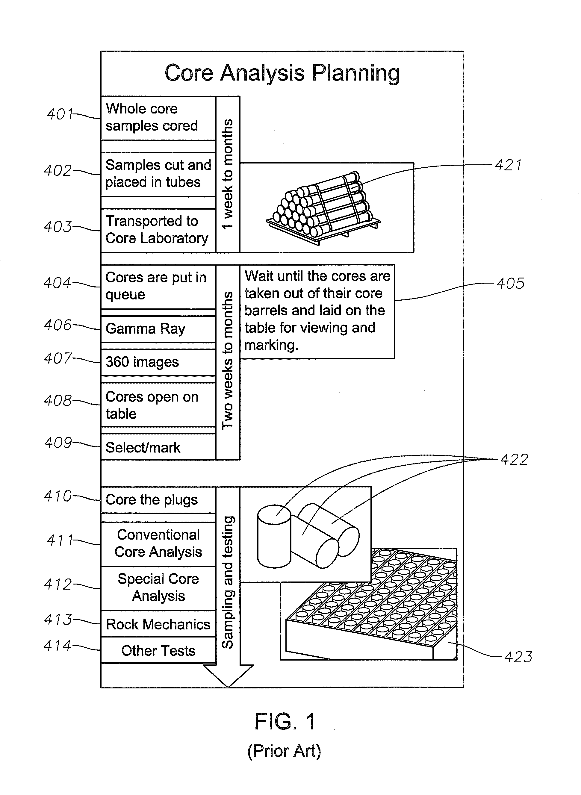
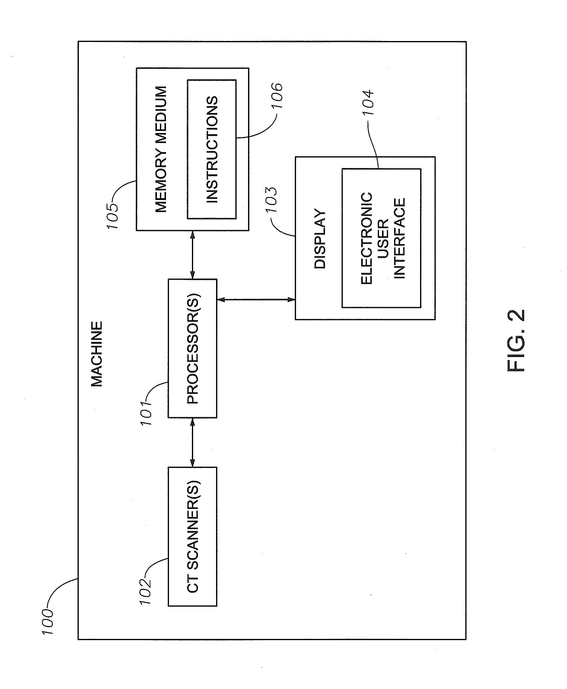
[0048]So that the manner in which the features and advantages of the embodiments of methods, machines, systems, and non-transitory computer-readable medium having computer program stored therein of the present disclosure, as well as others, which will become apparent, may be understood in more detail, a more particular description of the embodiments of methods, machines, systems, and non-transitory computer-readable medium having computer program stored therein of the present disclosure briefly summarized supra may be had by reference to the embodiments thereof, which are illustrated in the appended drawings, which form a part of this specification. It is to be noted, however, that the drawings illustrate only various embodiments of the embodiments of methods, machines, systems, and non-transitory computer-readable medium having computer program stored therein of the present disclosure and are therefore not to be considered limiting of the embodiments of methods, machines, systems, ...


PUM


Abstract

Embodiments of the disclosure include methods, machines, and non-transitory computer-readable medium having one or more computer programs stored therein to enhance core analysis planning for a plurality of core samples of subsurface material. Embodiments can include positioning electronic depictions of structure of encased core samples of subsurface material on a display and determining portions of each of the images as different planned sample types thereby to virtually mark each of the images. Planned sample types can include, for example, full diameter samples, special core analysis samples, conventional core analysis samples, and mechanical property samples. Embodiments further can include transforming physical properties of encased core samples of subsurface material into images responsive to one or more penetrative scans by use of one or more computerized tomography (CT) scanners.

Description

CROSS-REFERENCE TO RELATED PATENT APPLICATIONS[0001]This application claims priority from U.S. Provisional Application No. 62 / 186,937, filed Jun. 30, 2015, and titled “CORED ROCK ANALYSIS PLANNING THROUGH CT IMAGES.” For purposes of United States patent practice, this application incorporates the contents of the Provisional application by reference in its entirety.BACKGROUND[0002]Field of the Disclosure[0003]Embodiments of the disclosure relate to hydrocarbon reservoir production and, more specifically, to methods, machines, and non-transitory computer-readable medium having computer program stored therein to enhance core sample analysis planning.[0004]Description of the Related Art[0005]During rock coring in development and exploration of a hydrocarbon reservoir to produce hydrocarbons, such as oil and gas, rock core samples of subsurface material are collected. The process of obtaining these samples, called cores or core samples, produces a corebore hole that is formed into and de...

Claims


Application Information

Patent Timeline
IPC IPC(8): G06T17/05G06T7/00
CPCG01N33/24G01N23/083E21B25/00G06T7/00G06T17/05G06T2200/24G06T2207/10081G06T2207/20221G06T2207/30181G06T2207/30204
Inventor CALISKAN, SINANSHEBATALHAMD, ABDULLAH M.
Owner SAUDI ARABIAN OIL CO
Features
  • Generate Ideas
  • Intellectual Property
  • Life Sciences
  • Materials
  • Tech Scout
  • Unparalleled Data Quality
  • Higher Quality Content
  • 60% Fewer Hallucinations
Learn More