
Connector and connector device

a technology of connectors and connectors, applied in the direction of vehicle connectors, coupling device connections, connections effected by permanent deformation, etc., can solve the problems of excessive force applied to the lock arm, lock arm is turned up, contact portion wear is very high, etc., and achieve the effect of reducing the wear of the contact portion due to vibration of the conta

Active Publication Date: 2017-01-05
PANASONIC INTELLECTUAL PROPERTY MANAGEMENT CO LTD
View PDF14 Cites 6 Cited by
  • Summary
  • Abstract
  • Description
  • Claims
  • Application Information

AI Technical Summary

Benefits of technology

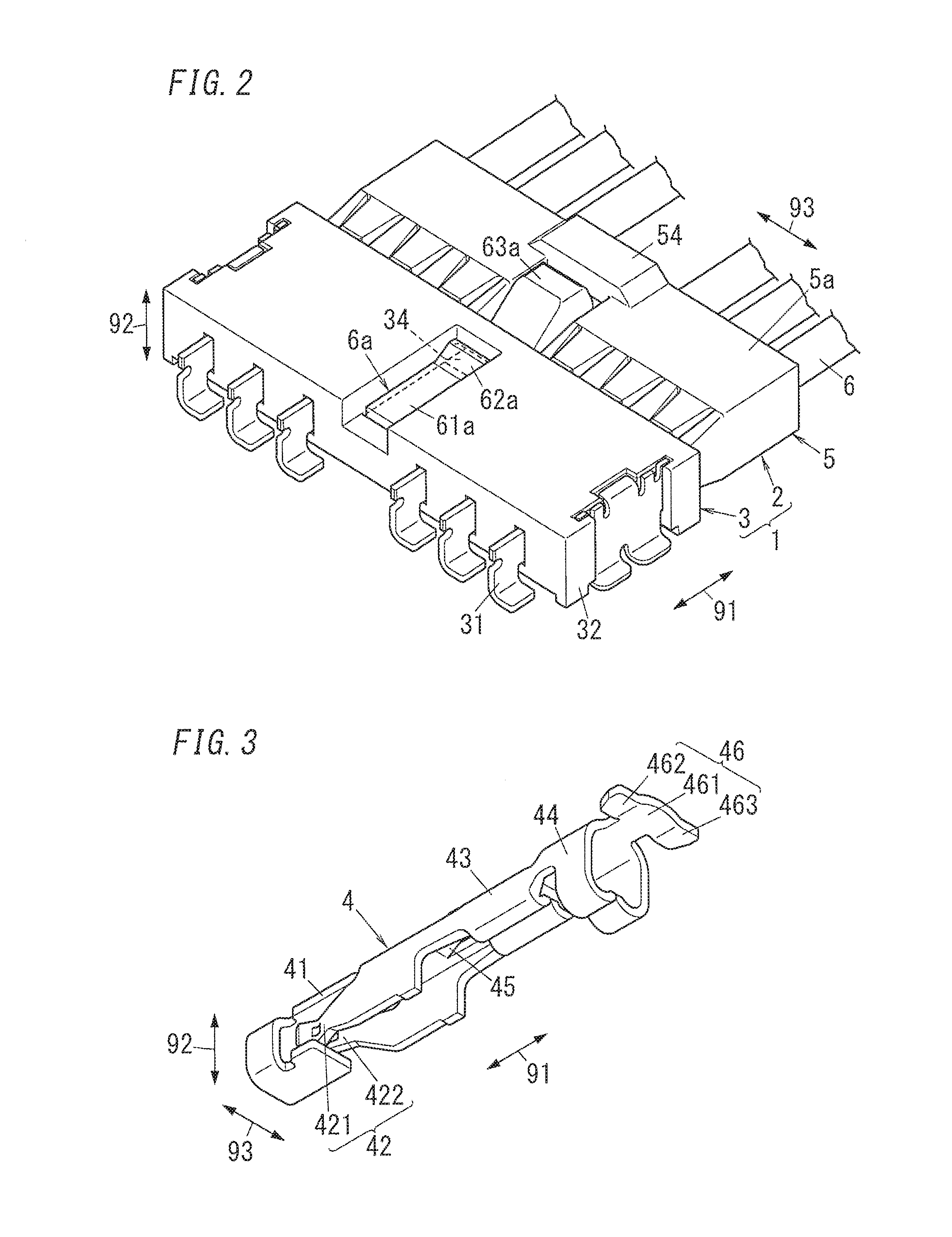
The present invention is a connector that reduces wear of the contact due to vibration. The connector has a contact with an elongated shape that is attached to an electrical wire. The contact has a contact portion that connects to an electrically conductive member, a connection portion that connects to the core wire of the electrical wire, a fixing portion that fixes the covering of the electrical wire, and a protruding portion that reduces the movement of the contact inside the connector. Overall, the connector reduces wear and tear on the contact and improves durability.

Problems solved by technology

Therefore, there is a problem in that wear of the contact portion occurs in the conventional connector, in particular, in the case where the connector device is mounted on a car, tile vibration that occurs in the contact is frequent and large, and as a result, the possibility of the contact portion of the contact being worn away becomes very high.
Incidentally, because the rear end portion of the lock arm is free in such a connector, in the case where a hand or an object catches on the rear end portion of the lock arm, it is possible that the lock arm is turned up or an excessive force is applied to the lock arm.

Method used


Image

  • Connector and connector device
  • Connector and connector device
  • Connector and connector device

Examples


Embodiment Construction

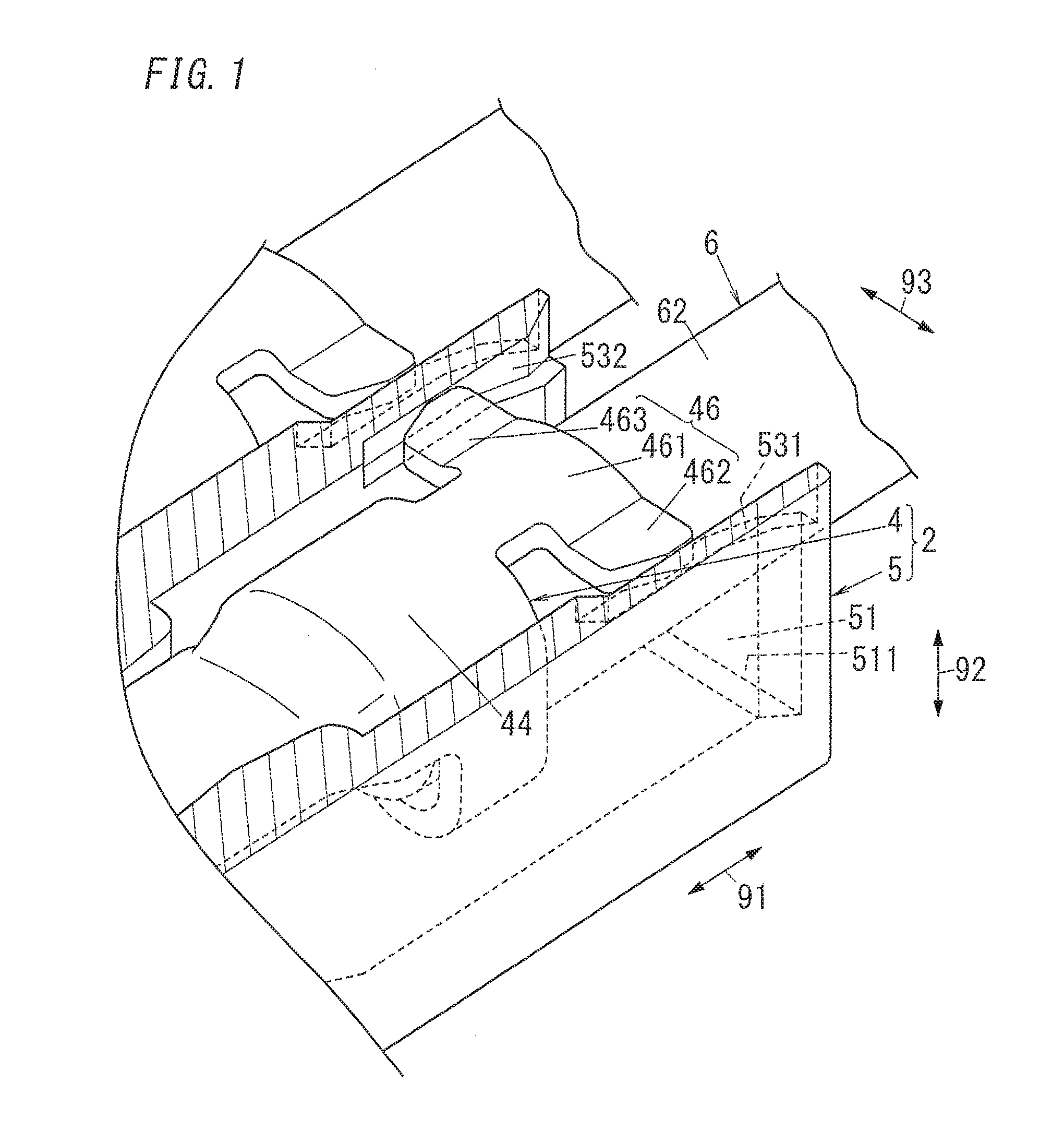
[0050]In a connector (plug connector according to the following embodiment, a contact includes a protruding portion on a side opposite to a connection portion relative to a fixing portion in a longitudinal direction of the contact, and the protruding portion reduces the positional displacement of a contact portion of the contact inside a housing.

[0051]Hereinafter, details of the plug connector and a connector device according to the present embodiment will be described with reference to the drawings.

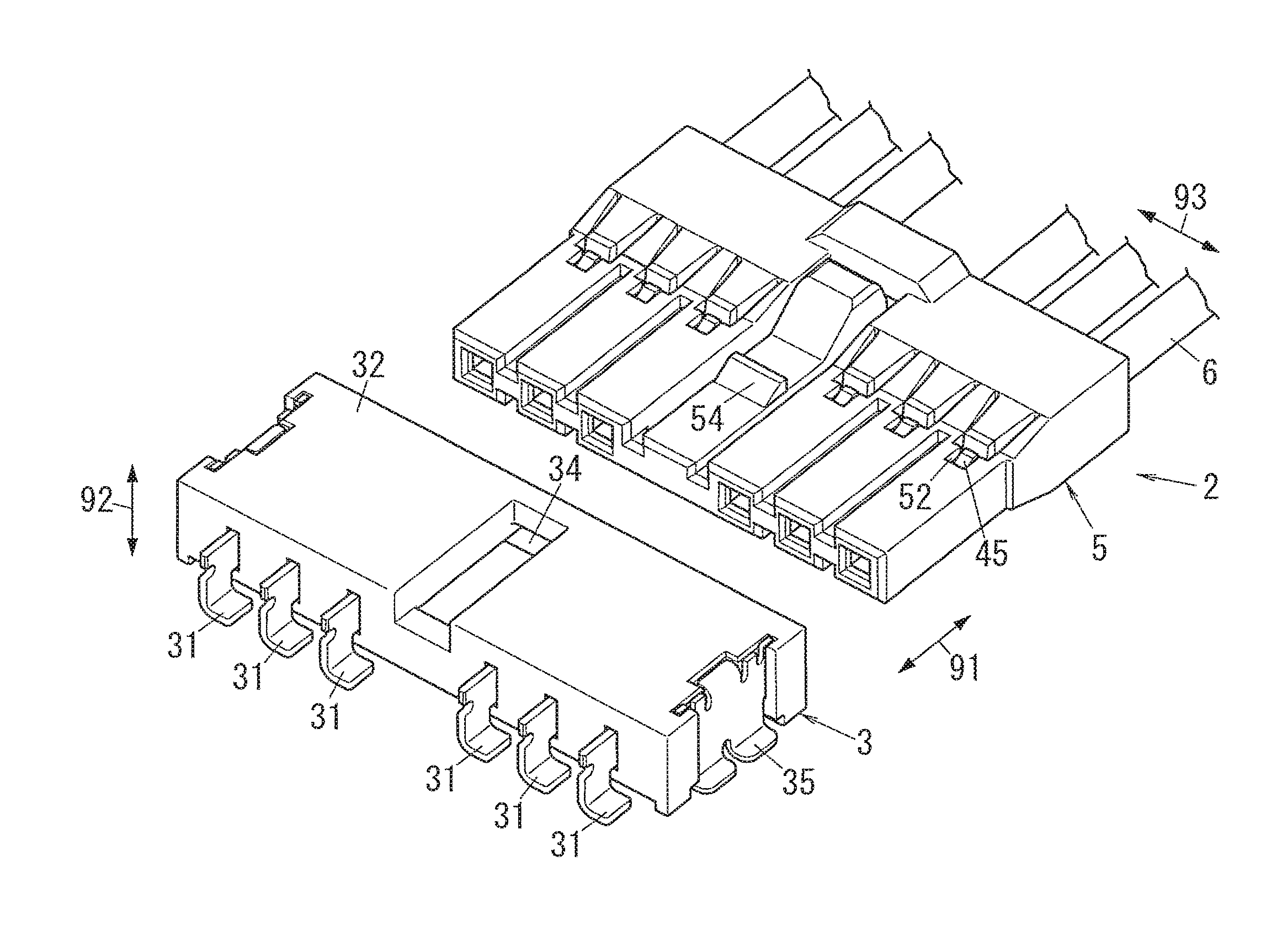
[0052]A connector device 1 according to the present embodiment includes a plug connector (connector) 2 and a receptacle connector (partner member) 3 to which the plug connector 2 is to he coupled (fitted), as shown in FIG. L. The connector device 1 is used for connecting an electrical wire 6 and a board 72 (refer to FIG. 8) in a vehicle such as a car, for example. The connector device 1 is a so-called wire-to-board connector device. Note that the application of the connector device 1 is ...


PUM


Abstract

A connector includes a contact in an elongated shape that is electrically conductive, and a housing that has an internal space is formed. The contact includes a contact portion, a connection portion, a fixing portion, and a protruding portion. The contact portion is to be electrically connected to an electrically conductive member when the contact is housed in the housing. The connection portion is electrically connected to a core wire of an electrical wire. The fixing portion is provided on a side opposite to the contact portion relative to the connection portion, and fixes a covering of the electrical wire. The protruding portion is provided on an end portion side of the fixing portion opposite to the connection portion so as to protrude. The protruding portion reduces the amount of movement of the contact inside the internal space of the housing.

Description

TECHNICAL FIELD[0001]This invention, in general, relates to connectors and connector devices, and specifically relates to a connector to he used for connecting an electrical wire and a board and a connector device including this connector.BACKGROUND ART[0002]Heretofore, connector devices to he used for connecting an electrical wire and aboard are known. A contact is attached to a tip of the electrical wire. A conventional connector device includes a plug connector in which the contact is inserted into a housing, and a receptacle connector that is to be mounted to the board,[0003]A contact to be used for such a connector device is disclosed in JP H06-223665 A (hereinafter referred to as “Document 1”), for example. A plug connector in a state in which the contact attached to an electrical wire is inserted into a housing is inserted into a receptacle connector, and as a result, the contact in the plug connector is electrically connected to a post in the receptacle connector. Accordingl...

Claims


Application Information

Patent Timeline
Patent Type & Authority Applications(United States)
IPC IPC(8): H01R13/533H01R4/18H01R12/75H01R13/432H01R13/627
CPCH01R13/533H01R4/185H01R12/75H01R13/4223H01R13/432H01R13/6272H01R13/639H01R24/60H01R2201/26
Inventor TAGUCHI, HIDETAKAOKURA, KENJIIIDA, MITSURUITO, CHIKARA
Owner PANASONIC INTELLECTUAL PROPERTY MANAGEMENT CO LTD
Learn More