Air column bag equipment driving unit and air column bag machining equipment thereof

A technology of equipment driving and processing equipment, which is applied in the field of machinery, can solve problems affecting production capacity, unreasonable design, and high maintenance difficulty, and achieve the effects of increasing production capacity, reducing processing and manufacturing difficulty, and optimizing compactness

Active Publication Date: 2020-03-31
浙江华鲲科技有限公司
View PDF8 Cites 2 Cited by
  • Summary
  • Abstract
  • Description
  • Claims
  • Application Information

AI Technical Summary

Problems solved by technology

[0004] The defect of this kind of equipment is: for the maintenance of the lifting power, it needs to be embedded in the bottom of the equipment to complete the maintenance or repair. The design is very unreasonable and the maintenance is difficult, which seriously affects the production capacity.

Method used


Image

  • Air column bag equipment driving unit and air column bag machining equipment thereof
  • Air column bag equipment driving unit and air column bag machining equipment thereof
  • Air column bag equipment driving unit and air column bag machining equipment thereof

Examples


Embodiment 1

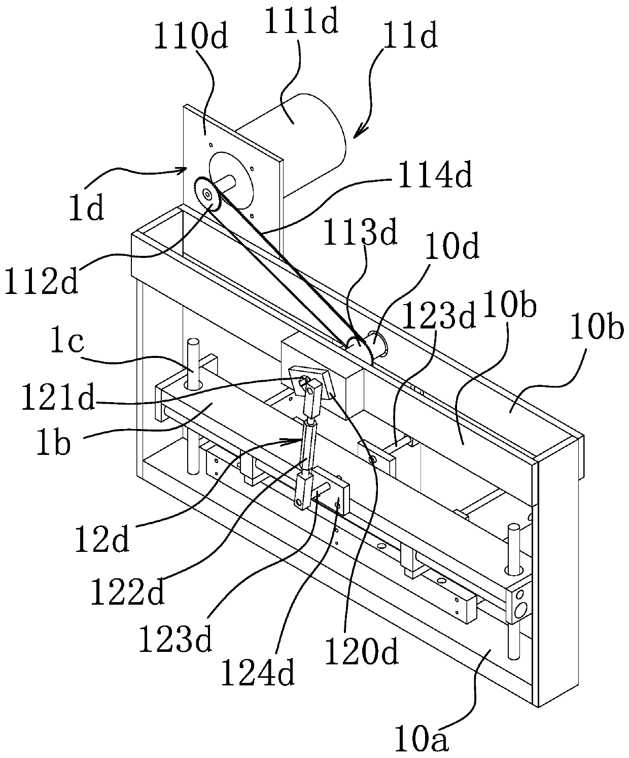
[0058] Such as figure 2 As shown, the driving unit of the air column bag equipment includes a fixed outer frame 1a, and the fixed outer frame 1a is vertically fixed on the frame 1;

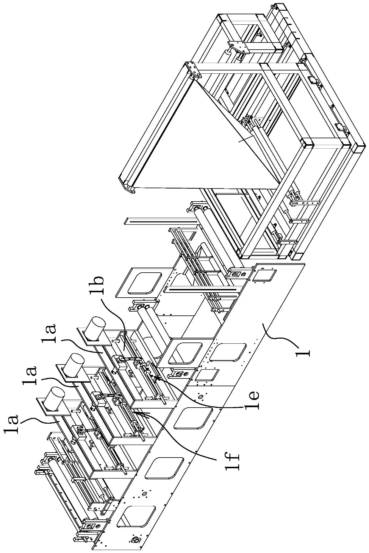
[0059] Such as image 3 As shown, the actuator mounting plate 1b, the actuator mounting plate 1b is horizontally located in the fixed outer frame 1a and can be lifted in the vertical direction;

[0060] The vertical guide mechanism 1c is connected to the actuator mounting plate 1b and the fixed outer frame 1a, and is used to improve the lifting stability of the actuator mounting plate 1b;

[0061] Lifting drive mechanism 1d, the lifting drive mechanism 1d is fixed on the top of the fixed outer frame 1a and connected to the middle of the actuator mounting plate 1b, and the lifting drive mechanism 1d drives the actuator mounting plate 1b to reciprocate up and down in the vertical direction.

[0062] Further, the lifting drive mechanism 1d is an eccentric lifting drive mechanism.

[0063] Specifi...

Embodiment 2

[0132] The principle of this embodiment is basically the same as Embodiment 1, and the different structures are:

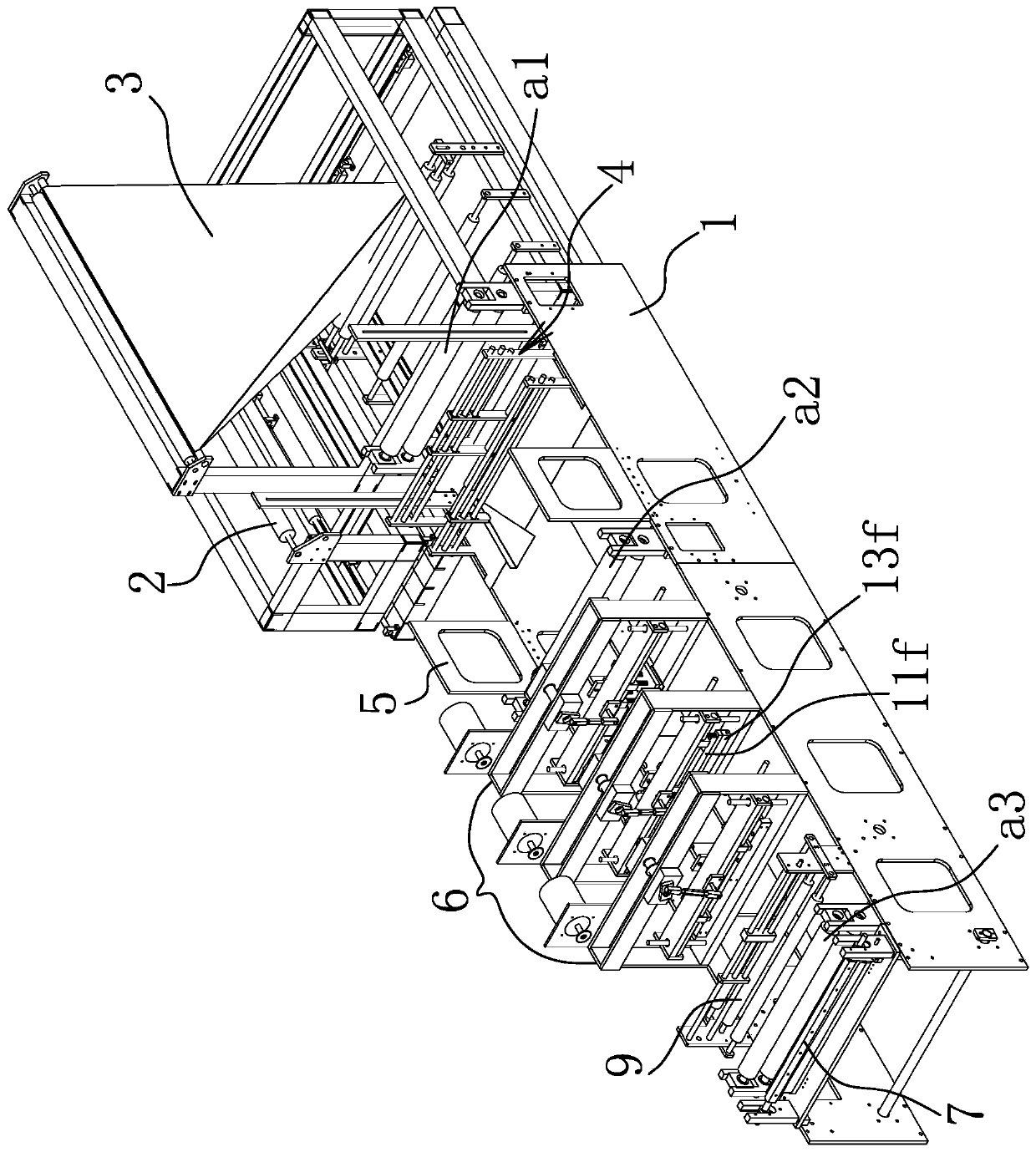
[0133] Such as Figure 13 As shown, the air column bag processing equipment includes a frame 1, and an unwinding unit 2, a corner folding unit 3, a hemming unit 4, a material storage unit 5, a processing unit 6 and a winding unit 8 are sequentially arranged on the frame 1, The processing unit 6 includes at least three fixed outer frames 1a and is sequentially fixed on the frame, and the fixed outer frames 1a are vertically fixed on the frame 1;

[0134] The actuator mounting plate 1b, the actuator mounting plate 1b is horizontally located in the fixed outer frame 1a and can be raised and lowered in the vertical direction;

[0135] The vertical guide mechanism 1c is connected to the actuator mounting plate 1b and the fixed outer frame 1a, and is used to improve the lifting stability of the actuator mounting plate 1b;

[0136] Lifting drive mechanism 1d, the lifti...


PUM


Abstract

The invention belongs to the technical field of machines, and particularly relates to an air column bag equipment driving unit and air column bag machining equipment thereof. The technical problem that in the prior art, maintenance is not convenient is solved. The air column bag equipment driving unit comprises an outer fixing frame, an executing mechanism installing plate, a vertical guiding mechanism and a lifting driving mechanism, wherein the outer fixing frame is vertically fixed to the rack, the executing mechanism installing plate is horizontally placed inside the outer fixing frame andcan ascend and descend in the vertical direction, the vertical guiding mechanism is connected to the executing mechanism installing plate and the outer fixing frame and used for improving the liftingstability of the executing mechanism installing plate, the lifting driving mechanism is fixed to the top of the outer fixing frame and is connected with the middle of the executing mechanism installing plate, and the lifting driving mechanism drives the executing mechanism installing plate to ascend and descend in a reciprocating mode in the vertical direction. The air column bag equipment driving unit has the advantage of being convenient to maintain.

Description

technical field [0001] The invention belongs to the technical field of machinery, and in particular relates to an air column bag equipment driving unit and an air column bag processing equipment thereof. Background technique [0002] Air column bags, which can be used to package products to avoid product damage due to bumps and collisions during transportation or handling. [0003] The processing and manufacturing of air column bags is carried out by mechanical equipment. In traditional mechanical equipment of this type, processing units such as air channel edge sealing, edge sealing and point knives use symmetrical lifting power on both sides of the frame to control the air channel. The edge banding, edge banding and point knives are lifted, and this lifting power is installed inside the frame and below the air channel edge banding, edge banding and point knives. [0004] The defect of this kind of equipment is: for the maintenance of the lifting power, it needs to be embe...

Claims


Application Information

Patent Timeline
Patent Type & Authority Applications(China)
IPC IPC(8): B31B70/00B31B70/74B31B70/26B31B70/20B31B70/64B31B70/81
CPCB31B70/00B31B70/74B31B70/26B31B70/20
Inventor 林瑞锋张秀
Owner 浙江华鲲科技有限公司
Why Eureka
Try Eureka