Tripod type constant velocity joint

a constant velocity joint, tripod technology, applied in the direction of yielding couplings, rotary machine parts, couplings, etc., can solve the problems of premature wear of the contact region, increased contact surface pressure, and reduced performance, so as to achieve the effect of reducing wear

Active Publication Date: 2010-04-27
NTN CORP
View PDF20 Cites 2 Cited by
  • Summary
  • Abstract
  • Description
  • Claims
  • Application Information

AI Technical Summary

Benefits of technology

[0006]The present invention is intended to eliminate such problems. That is, the object of the invention is to provide a tripod type constant velocity joint given a construction such that a recovery couple is produced to correct the inclination of the rolling direction of the roller while reducing the surface pressure without using angular contact provided by a Gothic arch-shaped roller guide surface and such that the NVH characteristic is maintained for a long time.
[0008]This setting makes it possible to provide a contact angle over the entire width of the roller and to increase the recovery couple during torque load. Further, the solid contact occurring in the high load region greatly reduces the contact surface pressure to reduce wear of the contact section. In the above setting, the radius of curvature r of the generatrix for the outer peripheral surface of the roller has its allowable range defined to be up to a value slightly smaller than the radius of curvature R of the roller guide surface. Since the roller is of torus shape, an inclination of the roller in the rolling direction results in the same state as the setting r>R, that is, the area of the roller adjacent its widthwise middle separates from the roller guide surface and instead the areas of the roller adjacent its widthwise opposite ends contact the roller guide surface.
[0010]The widthwise opposite ends of the outer peripheral surface of the roller may be provided with roundings having a radius of curvature smaller than the radius of curvature of the generatrix in the direction away from the roller guide groove, thereby making it possible to avoid edge load at a widthwise end of the roller.
[0011]According to the invention, it is possible to generate a large recovery couple to correct the inclination of the rolling direction of the roller without using angular contact provided by a Gothic arch-shaped roller guide surface and since the contact surface pressure can be reduced, wear is reduced, so that the NVH characteristic can be maintained for a long time.

Problems solved by technology

Doing so will result in an increase in contact surface pressure, which would sometimes cause premature wear of the contact region.
Either case leads to a lowering in performance, sometimes causing a shudder to occur in a vehicle having the joint mounted thereon.

Method used


Image

  • Tripod type constant velocity joint
  • Tripod type constant velocity joint
  • Tripod type constant velocity joint

Examples


Embodiment Construction

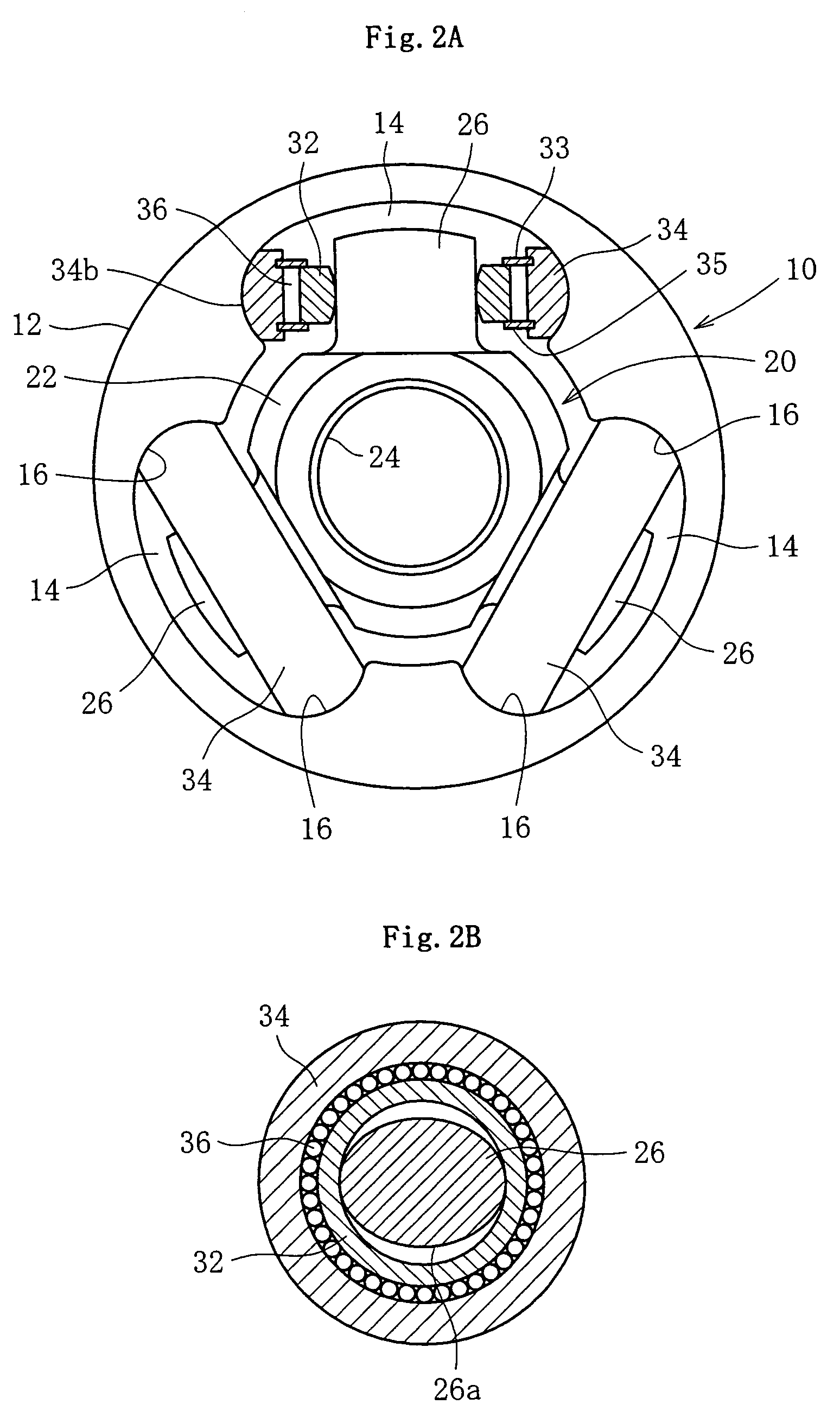
[0021]Embodiments of the invention exemplified in the drawings will now be described. First, referring to FIGS. 2A, 2B and 3, the basic construction of a tripod type constant velocity joint will be described. FIG. 2A is an end view of a joint shown partly in section. FIG. 2B is a cross sectional view of a trunnion and a roller assembly. FIG. 3 is a longitudinal sectional view of the joint taking an operating angle θ. As shown, the constant velocity joint comprises an outer joint member 10 and a tripod member 20, wherein one of the two shafts to be connected is connected to the outer joint member 10 and the other is connected to the tripod member 20. The outer joint member 10 comprises a bottomed cylindrical mouth section 12 and a stem section 18, the stem section 18 being in the form of a serrated shaft, through which the outer joint member is connected to one of the two shafts to be connected. Axially extending track grooves 14 are formed at three equispaced positions on the circum...


PUM


Abstract

In a tripod type constant velocity joint, in order to produce a recovery couple to correct the inclination of the rolling direction of a roller and to reduce surface pressure without using angular contact provided by a Gothic arch-shaped roller guide surface, it is arranged that where r1 and r2 are the minimum and maximum values, respectively, of the radius of curvature of the generatrix for the outer peripheral surface of the roller within the range where solid contact is effected by elastic deformation of the contact section between the roller and the roller guide surface under a predetermined torque load with respect to the radius of curvature of the roller guide surface, the radius of curvature (r) of the generatrix be set in the range r1≦r≦r2.

Description

BACKGROUND OF THE INVENTION[0001]1. Field of the Invention[0002]This invention relates to a tripod type constant velocity joint, which can be utilized for power transmission in automobiles and various industrial machines. For example, it may be incorporated into the driving system of an automobile to effect transmission of a turning force at constant angular velocity between rotary shafts which are in a non-straight line.[0003]2. Description of the Prior Art[0004]As regards means for solving the problem of shudder in vehicles concerning rotation third-order axial force in tripod type constant velocity joints, tripod type constant velocity joints which are of the so-called double roller type in which an outer roller 4 rolls in parallel with the axis of an outer joint member 1 along a track groove 2 in the outer joint member 1 are described in, for example, Japanese Patent Publication (Kouhyou) Heisei 4-503554 and Japanese Patent Publication (Koukai) Heisei 5-215141 (see FIG. 7). In t...

Claims


Application Information

Patent Timeline
Patent Type & Authority Patents(United States)
IPC IPC(8): F16D3/26F16D3/205
CPCF16D3/2055F16D2003/2026F16D2003/2023Y10S464/905
Inventor IZUMINO, JUNICHIYAMAZAKI, KENTA
Owner NTN CORP
Why Eureka
Try Eureka