Battery Control Apparatus

a battery control and battery technology, applied in the field of battery control apparatus, can solve the problems of difficulty in maximizing cost benefits, and the difference of electricity bill with respect to the introduction cost of the battery by the discharge of the battery, so as to achieve the effect of maximizing battery cost benefits and reducing battery cos

Active Publication Date: 2017-01-05
HITACHI LTD
View PDF7 Cites 3 Cited by
  • Summary
  • Abstract
  • Description
  • Claims
  • Application Information

AI Technical Summary

Benefits of technology

[0005]In JP-A-2009-194947, a charge and discharge management apparatus and a method for changing the charge and discharge depth according to increment and decrement of the electric, power demand are described. However, it is difficult to maximize cost benefits of the battery in a case or the like whe...

Problems solved by technology

However, it is difficult to maximize cost benefits of the battery in a case or the like where since a life span of the battery and an electricity unit cost which is set higher than a normal state at a time in which supply of the electric power is tight are not considered, a difference of an electricit...

Method used


Image

  • Battery Control Apparatus
  • Battery Control Apparatus
  • Battery Control Apparatus

Examples


first embodiment

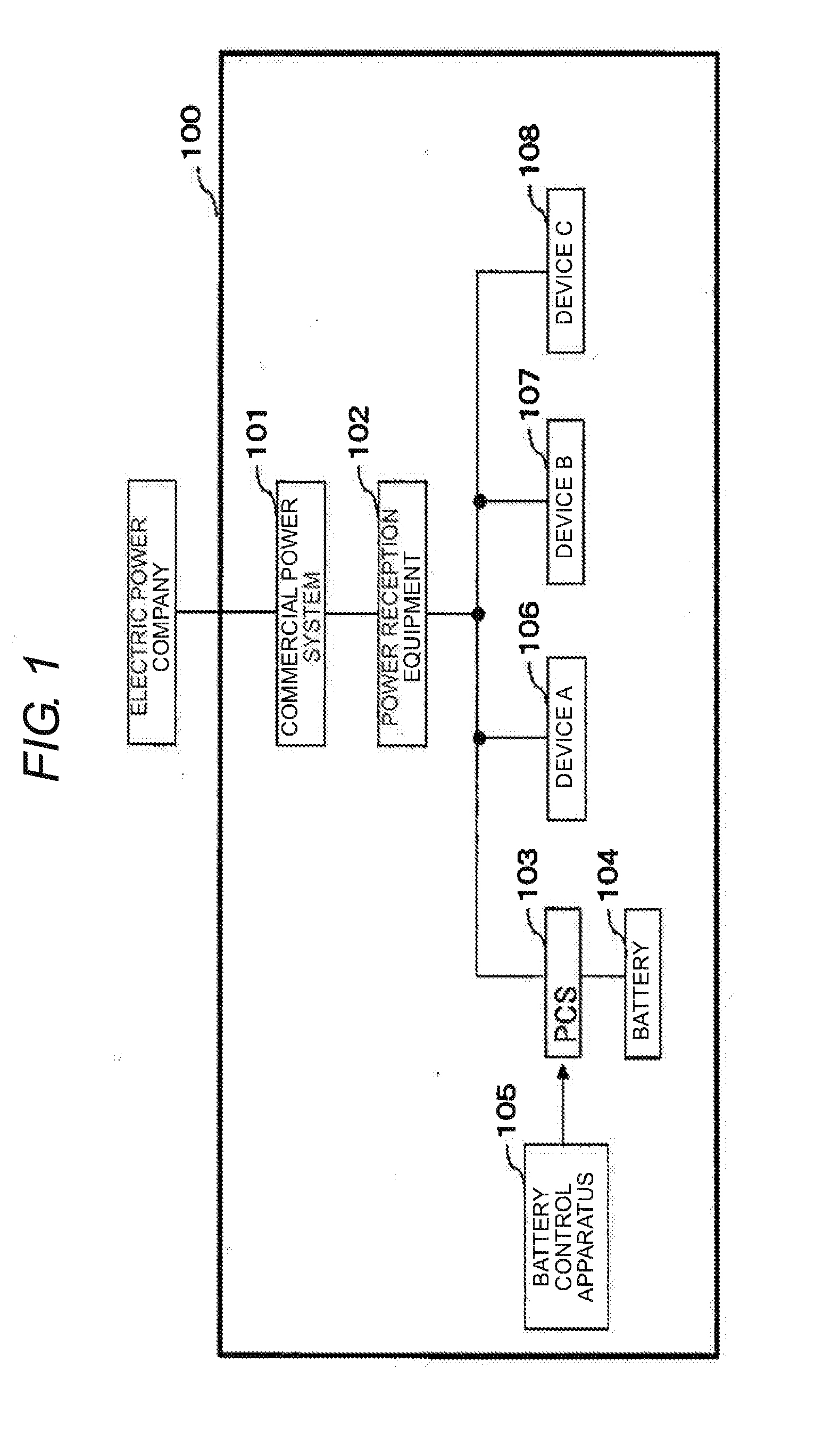
[0024]FIG. 1 is a configuration diagram of electric power equipment of customer facilities and devices within the facilities according to an embodiment of the invention.

[0025]As illustrated in FIG. 1, a customer facility 100 includes a commercial power system 101, power reception equipment 102, a power conditioning system (PCS) 103, a battery 104, a battery control apparatus 105, a device A 106, a device B 107, and a device C 108.

[0026]The commercial power system 101 includes electric power supplied from thermal power generation, hydroelectric power generation, nuclear power generation, wind power generation, or the like of electric power companies, or the like to a customer

[0027]The power reception equipment 102 is equipment of converting the electric power supplied from the commercial power system 101 to the customer facility into electricity suitable for devices of the customer facility.

[0028]The PCS 103 is a device provided in the battery 104, and a device of converting AC elect...

second embodiment

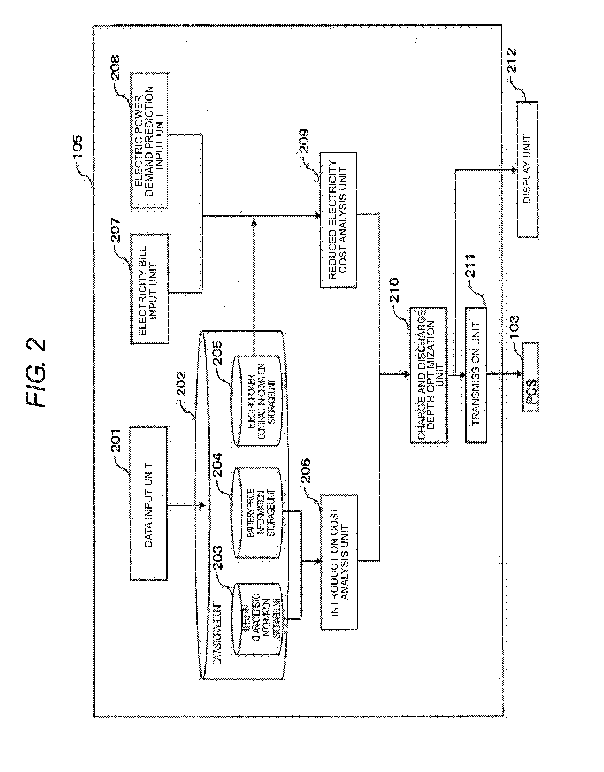
[0102]In the embodiment, an example of a battery control apparatus in which when the reduced electricity cost is calculated in the reduced electricity cost analysis unit 209, the reduced electricity cost is calculated by considering conditions from outside and charge and discharge depth is optimized, will be described.

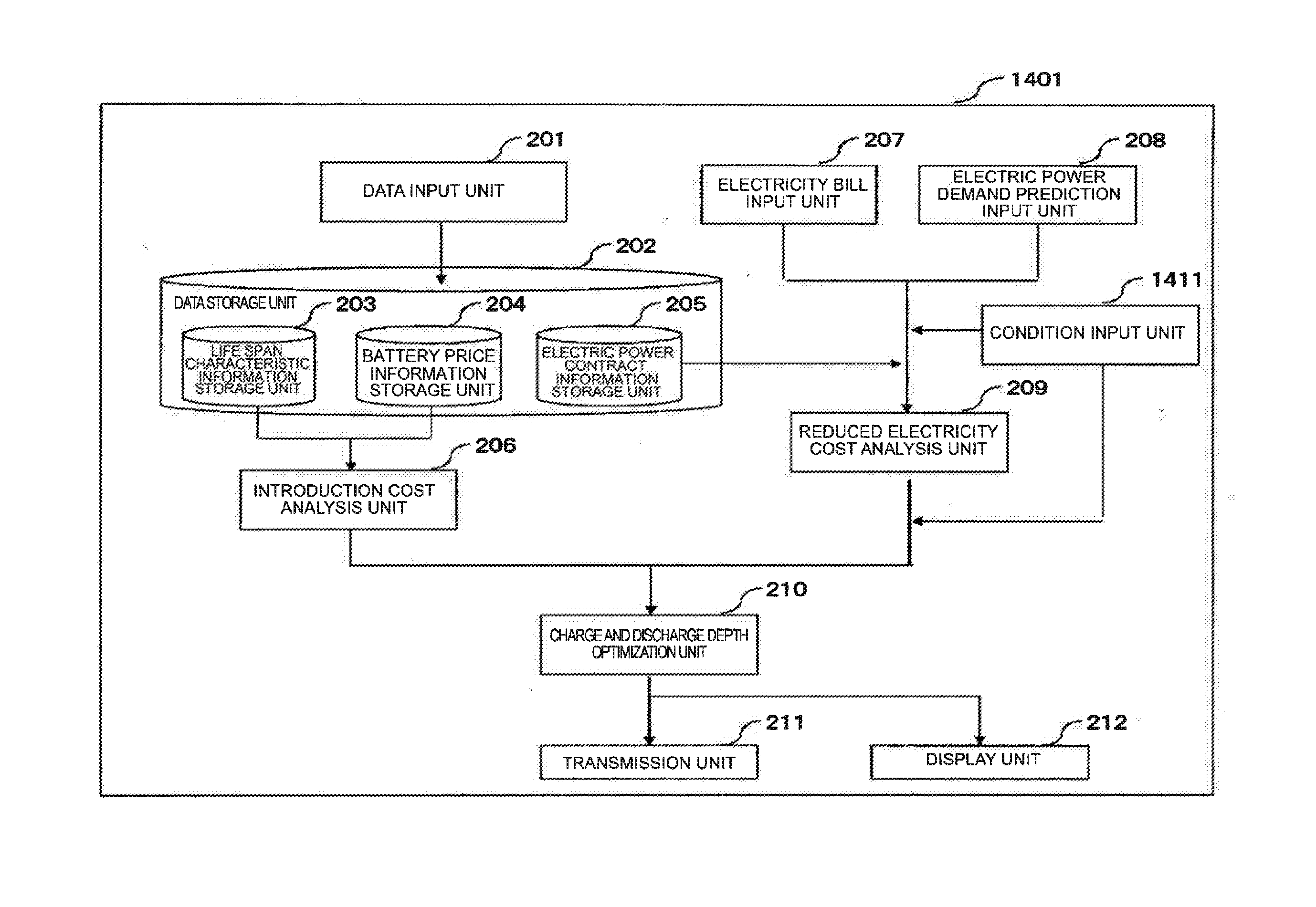
[0103]FIG. 14 is an example of a configuration diagram of a battery control apparatus 1401 in a second embodiment.

[0104]In the battery control apparatus 1401 of FIG. 14, description of parts having configurations and the same function including the same reference numerals illustrated in FIG. 2 will not be repeated. The battery control apparatus 1401 newly includes a condition input unit 1411.

[0105]The condition input unit 1411 receives a condition given from outside when the reduced electricity cost is calculated. The condition, for example, is an upper limit of the electric power demand. set by the customer based. on a reduction of the basic cost of electricity in the...


PUM


Abstract

A battery control apparatus includes a reduced electricity cost analysis unit that obtains a discharge electric power cost at a discharge time and a charge electric power cost at a charge time of a battery, based on a basic cost and a unit cost of an electricity bill, and obtains a reduced electricity cost in which the charge electric power cost is subtracted from the discharge electric power cost for every discharge depth of the battery; an introduction cost analysis unit that calculates an introduction cost of the battery for every discharge depth of the battery; and a charge and discharge depth optimization unit that obtains a difference of the reduced electricity cost and the introduction cost for every discharge depth of the battery, and determines a charge and discharge depth of the battery based. on the difference. The discharge of the battery is performed at the determined charge and discharge depth.

Description

BACKGROUND OF THE INVENTION[0001]Field of the Invention[0002]The present invention relates to a battery control apparatus.[0003]Background Art[0004]A life span of a battery depends on the discharge depth of the battery, that is, whether or not discharge is repeated at any degree of depth in a fully charged state. For example, even when the discharge is repeated at a deep depth in a lithium battery, it is possible to improve cycle characteristics by repeating shallow discharge. Accordingly, in the related art, when the battery is used in the reduction of electric power demand of customer facilities in an energy management system, the discharge is performed by decreasing the charge and discharge depth. However, when the increment of the electric power demand is predicted, there is a need to improve discharge output by increasing the charge and discharge depth in order to increase the amount of reduction in the electric power demand. There is JP-A-2009-194947 as a background technology...

Claims


Application Information

Patent Timeline
IPC IPC(8): H02J7/00G06Q30/02G06Q50/06
CPCH02J3/32H02J3/008Y04S50/10Y04S50/14G06Q30/0283G06Q50/06H02J7/0048
Inventor MIYAKE, NORIYUKITOMITA, YASUSHIKAWAMURA, TSUTOMUTAKAHASHI, HIROTAKAKUWABARA, KENICHIHISAJIMA, DAISUKEYAMADA, JUNICHI
Owner HITACHI LTD
Why Eureka
Try Eureka