Method for producing parts

a polymer and production method technology, applied in the field of polymer production methods, can solve the problems of increasing the relative unit cost of parts of this type, mixing between parts, and complicating the essential requirement of traceability of parts for pharmaceutical and medical use, and achieve the effect of limiting the bulk of the tooling needed for production and rapid production

Active Publication Date: 2017-01-12
GRP JBT
View PDF10 Cites 0 Cited by
  • Summary
  • Abstract
  • Description
  • Claims
  • Application Information

AI Technical Summary

Benefits of technology

[0017]It is one objective of the invention to overcome these disadvantages. One particular objective of the invention is to propose a method and system to produce parts via injection allowing implementation of the production of parts of different geometries that are to be assembled, this production being rapid whilst limiting the bulk of the tooling needed for production.

Problems solved by technology

On the other hand, in some cases certain parts, typically thicker parts, require long solidification cycle times. These parts are therefore produced using multi-cavity tooling of large size to allow the large mass production of parts thereby increasing the relative unit cost of parts of this type.
In addition, any additional handling leads to risks of accidental mixing between parts and makes more complex the essential requirement of traceability of parts for pharmaceutical and medical use.

Method used


Image

  • Method for producing parts
  • Method for producing parts
  • Method for producing parts

Examples


first example

[0175]FIGS. 4A1 to 4D2 illustrate an example of a method for producing a part formed of two elements.

[0176]The part is a protective sheath for needles routinely used in the pharmaceutical field, in particular for syringes pre-filled with medication and intended to be incorporated for example in drug auto-injectors.

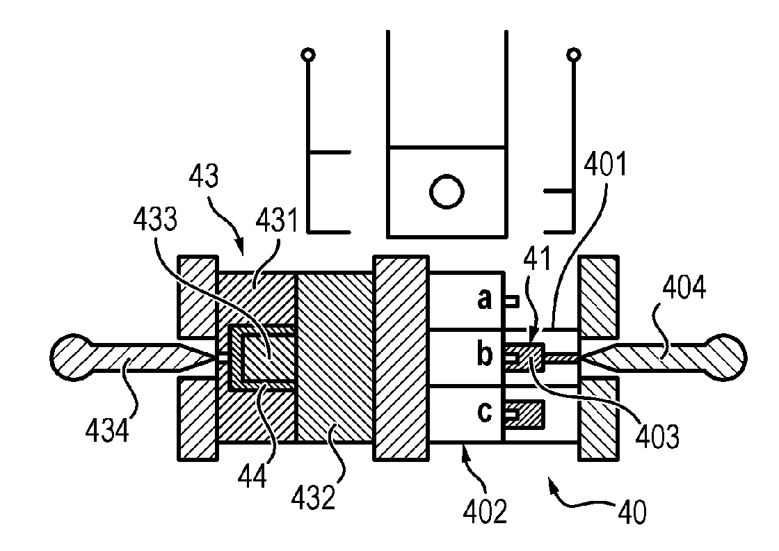
[0177]The part is typically composed of two elements. The first element 41 is an element in elastomer for example typically of cylindrical shape comprising an inner conical part intended to receive the needle. The second element 44 is typically a tubular part in rigid plastic covering the first element 41 and intended to rigidify this same more flexible first element 41.

[0178]The two elements are typically produced in equal quantities since they are intended to be assembled together in strict parity.

[0179]The first element 41 typically forms an inner part in elastomer and may comprise thicker parts typically in the order of 2.5 mm. The second element 44 typically forms a r...

second example

[0190]FIGS. 5A1 to 5E2 illustrate another example of a method for producing a part formed of two elements.

[0191]The parts also form a needle protection for example.

[0192]This example differs from the preceding example in that the solidification time of the first element 41 is typically substantially equal to three times the solidification time of the second element 44 intended to be assembled in parity with the first element 41.

[0193]The second element 44 is typically produced on a second mould 43 having n injection cavities, “n” being a positive integer, the first element 41 then typically being produced on a mould 40 of which the second mould portion 402 comprises 3×n ejection zones 4021, 4022 and 4023.

[0194]The first element 41 and the second element 44 are produced for example on injection moulding machines.

[0195]The machines are typically associated in tandem during production time, the produced first elements 41 and second elements 44 typically being immediately assembled toge...


PUM

PropertyMeasurementUnit
thicknessaaaaaaaaaa
thicknessaaaaaaaaaa
thicknessaaaaaaaaaa

Abstract

A method for producing parts from polymer in a mould comprising first and second mould portions that can be moved relative to each other, comprising: —closing (202) the mould in order to form a first injection cavity connected to an injection device by the first mould portion, —injecting (204) material into the first injection cavity in order to form a first part, —moving (206) one of the mould portions relative to the other, the first part remaining connected to the second mould portion, —closing (208) the mould to form: a second injection cavity connected to the injection device by the first mould portion, and a first solidification cavity in which the first part is disposed, —injecting (210) material into the second injection cavity to form a second part and simultaneously solidifying the first part disposed in the first solidification cavity.

Description

FIELD OF INVENTION[0001]The invention concerns a method for producing parts in polymer and an associated system. The invention particularly concerns the large mass production of such parts.STATE OF THE ART[0002]With reference to FIGS. 1A to 1D, a method for producing polymer parts by injection can be performed in a mould 100 comprising a fixed mould portion 101 and movable mould portion 102.[0003]The mould 100 is first closed to form a cavity connected via the fixed mould portion to a device 104 for the injection of material.[0004]As illustrated in FIG. 1A, material is then injected into the cavity 103 to form a first part 11. The mould 100 is held closed until the part 11 thus formed is fully solidified and is able to be ejected from the mould 100.[0005]As illustrated in FIG. 1B, the mould 100 is then opened.[0006]As illustrated in FIG. 1C, the solidified part 107 is then ejected and taken in charge by a robot 105.[0007]As illustrated in FIG. 1D, the robot 105 conveys the part 11 t...

Claims


Application Information

Patent Timeline
Patent Type & Authority Applications(United States)
IPC IPC(8): B29C45/04B29C45/72B29C45/32B29C45/00B29C45/16
CPCB29C45/04B29C45/006B29C45/1618B29L2031/7544B29C45/7207B29K2101/10B29K2101/12B29C45/32
Inventor BENOIT, JEANMALFROY, DOMINIQUELAVINA, LAURENT
Owner GRP JBT
Why Eureka
Try Eureka