Gas turbine engine blade with increased wall thickness zone in the trailing edge-hub region

a technology of trailing edge and hub region, which is applied in the direction of engine control, machine/engine, engine fuction, etc., can solve the problems of metal fatigue cracks in the blade substrate and crack propagation, and achieve the effect of reducing the thickness of the trailing edge (te) of the turbine engine blade, reducing the cyclic fatigue of the rotating mass, and increasing aerodynamic efficiency

Inactive Publication Date: 2017-01-12
SIEMENS ENERGY INC
View PDF10 Cites 11 Cited by
  • Summary
  • Abstract
  • Description
  • Claims
  • Application Information

AI Technical Summary

Benefits of technology

[0005]Despite conventional design wisdom to minimize turbine engine blade trailing edge (TE) thickness, in order to reduce rotating mass-induced cyclic fatigue and increase aerodynamic efficiency, local thickening of the airfoil outer or side wall zone in the region proximate the TE and hub actually reduces, rather than increases, peak stress at previously observed crack locations around the hub to airfoil wall TE region. Furthermore, increasing local thickening of the airfoil wall zone along the TE from the hub to approximately eight to ten percent (8-10%) of the airfoil stand length, which in some embodiments encompass typically the first five to eight TE pedestals, reduces likelihood of cracks at pedestal / side wall junction regions. Local thickening of the TE reduces the peak stress at the pedestal outer or side wall location and crack formation, which in turn enhances component service life. In cast turbine blades, the TE airfoil wall thickening zone not only reduces stress, but also enhances the casting alloy grain structure in a way to improve creep ductility, by changing the relative rates of solidification of the airfoil TE and the adjacent blade platform mass. The thickened TE zone drives the solidification relative rates in a way that enhances alloy grain structure and ductility, which beneficially retards crack propagation rate.

Problems solved by technology

Repetitive or cyclic loading of gas turbine engine blades during service operation may induce metal fatigue cracks in the blade substrate.
HCF is attributed to low-amplitude, high-frequency strains induced by blade flexure during engine operation, which can induce crack propagation during ongoing engine operation.

Method used


Image

  • Gas turbine engine blade with increased wall thickness zone in the trailing edge-hub region
  • Gas turbine engine blade with increased wall thickness zone in the trailing edge-hub region
  • Gas turbine engine blade with increased wall thickness zone in the trailing edge-hub region

Examples


Embodiment Construction

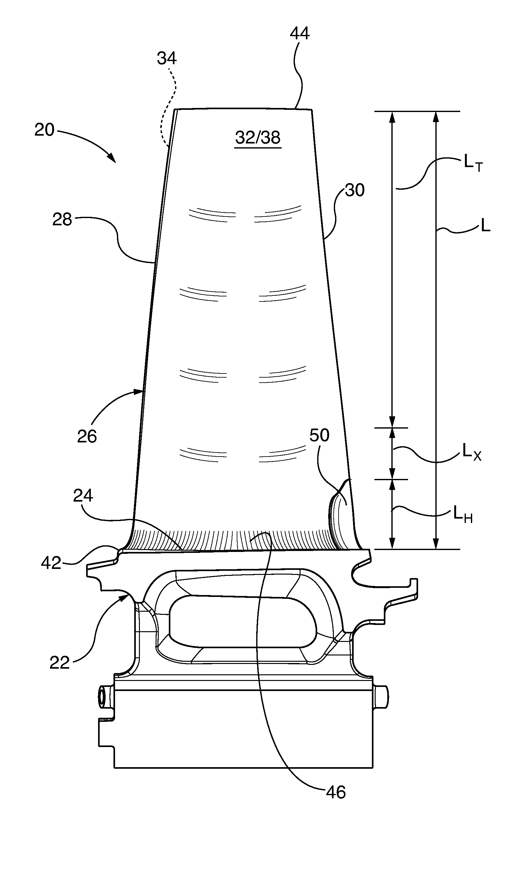
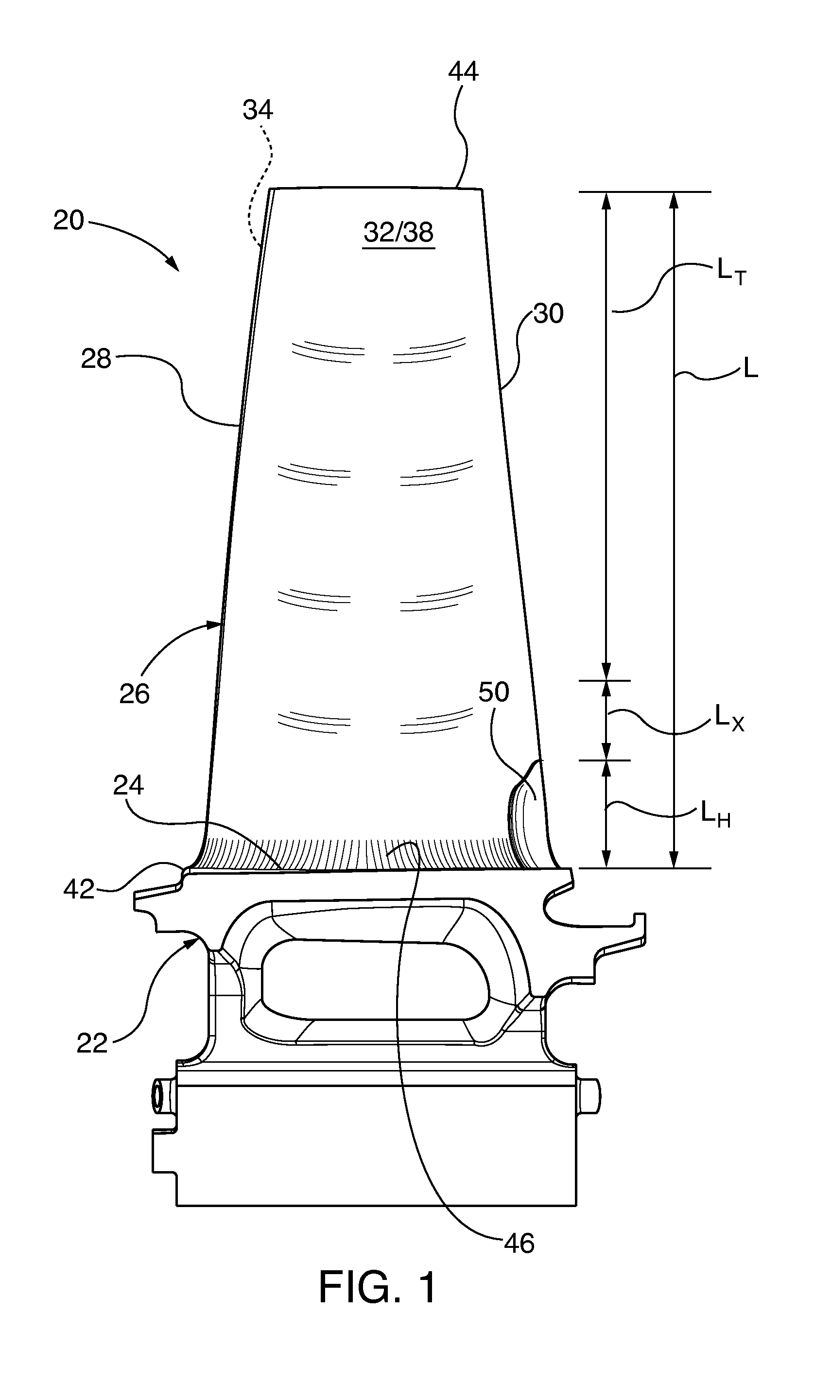
[0022]Exemplary embodiments of the invention are utilized in gas turbine engine rotating blades. More particularly, such blades having an increased airfoil outer wall or side wall thickness zone proximate the hub and trailing edge (TE), which reduces blade cracking propensity and enhances blade service life. Airfoil TE wall thickness in this zone proximate the hub is forty to sixty percent (40-60%) greater than the comparable greatest wall thickness anywhere else along the trailing edge from outboard that zone all the way to the blade tip. In many embodiments, the TE outer wall thickness proximate the blade tip and outboard or above the zone remains constant or tapers to reduced thickness along the span or stand length to the tip. The increased thickness zone generally comprises eight to ten percent (8-10%) of the total blade stand height. In some embodiments, the corresponding outer wall thickness in the increased thickness zone transitions from the thicker region proximate the hub...


PUM


Abstract

Airfoil outer wall thickness of a gas turbine engine blade is increased in the zone that is proximate the trailing edge and blade hub by forty to sixty percent (40-60%) greater than comparable greatest wall thickness anywhere else along the trailing edge from outboard that zone all the way to the blade tip. The increased thickness zone includes a transition zone that bridges the respective airfoil outer wall thicknesses proximate the hub and tip of the blade. Some embodiments also incorporate pedestals with compound curve fillets in the increased wall thickness zone. The increased thickness zone reduces blade cracking propensity and enhances service life.

Description

PRIORITY CLAIM[0001]This application claims the benefit of priority under U.S. Provisional Application No. 62 / 190,459, filed Jul. 9, 2015, and entitled “Blade for Gas Turbine Engine”, which is incorporated by reference herein.TECHNICAL FIELD[0002]The invention relates to gas turbine engine rotating blades. More particularly, the invention relates to gas turbine engine blades having an increased airfoil outer wall thickness zone proximate the hub and trailing edge (TE), which reduces blade-cracking propensity and enhances blade service life.BACKGROUND[0003]Repetitive or cyclic loading of gas turbine engine blades during service operation may induce metal fatigue cracks in the blade substrate. Commonly recognized fatigue mechanisms are thermo-mechanical fatigue (TMF), high-cycle fatigue (HCF) and low-cycle fatigue (LCF). TMF thermal strain is attributable to blade thermal expansion and contraction experienced during large temperature changes, such as induced during engine powering on ...

Claims


Application Information

Patent Timeline
Patent Type & Authority Applications(United States)
IPC IPC(8): F01D5/14F01D5/18
CPCF01D5/147F01D5/18F05D2260/2214F05D2240/304F05D2240/80F05D2220/32F05D2230/21F05D2260/941F05D2270/114
Inventor GUPTA, MOHITMOUNT, JONATHAN A.WIDRIG, SCOTT MICHAELANGAL, RAVISHANKAR P.
Owner SIEMENS ENERGY INC
Why Eureka
Try Eureka