Rotary electric machine stator

Active Publication Date: 2017-01-12
TOYOTA JIDOSHA KK
View PDF6 Cites 4 Cited by
  • Summary
  • Abstract
  • Description
  • Claims
  • Application Information

AI Technical Summary

Benefits of technology

[0013]Furthermore, in the rotary electric machine stator, the retainer member and the coil end may be fixed to each other via varnish. Consequently, the retainer member fixed via varni

Problems solved by technology

Rotary electric machines and the like installed in vehic

Method used


Image

  • Rotary electric machine stator
  • Rotary electric machine stator
  • Rotary electric machine stator

Examples


Embodiment Construction

[0021]An embodiment of the present disclosure will be described in detail below with reference to the drawings. The below description will be provided on a stator for a rotary electric machine to be installed in a vehicle, which is, however, is an example for description, and the stator may be any stator for a rotary electric machine that may be subjected to external vibration, other than those to be installed in vehicles. The materials, etc., mentioned below are examples for description and can arbitrarily be changed according to the specifications of the rotary electric machine stator. In the below, through all the drawings, components that are similar to each other will be provided with a same reference numeral, and overlapping description thereof will be omitted.

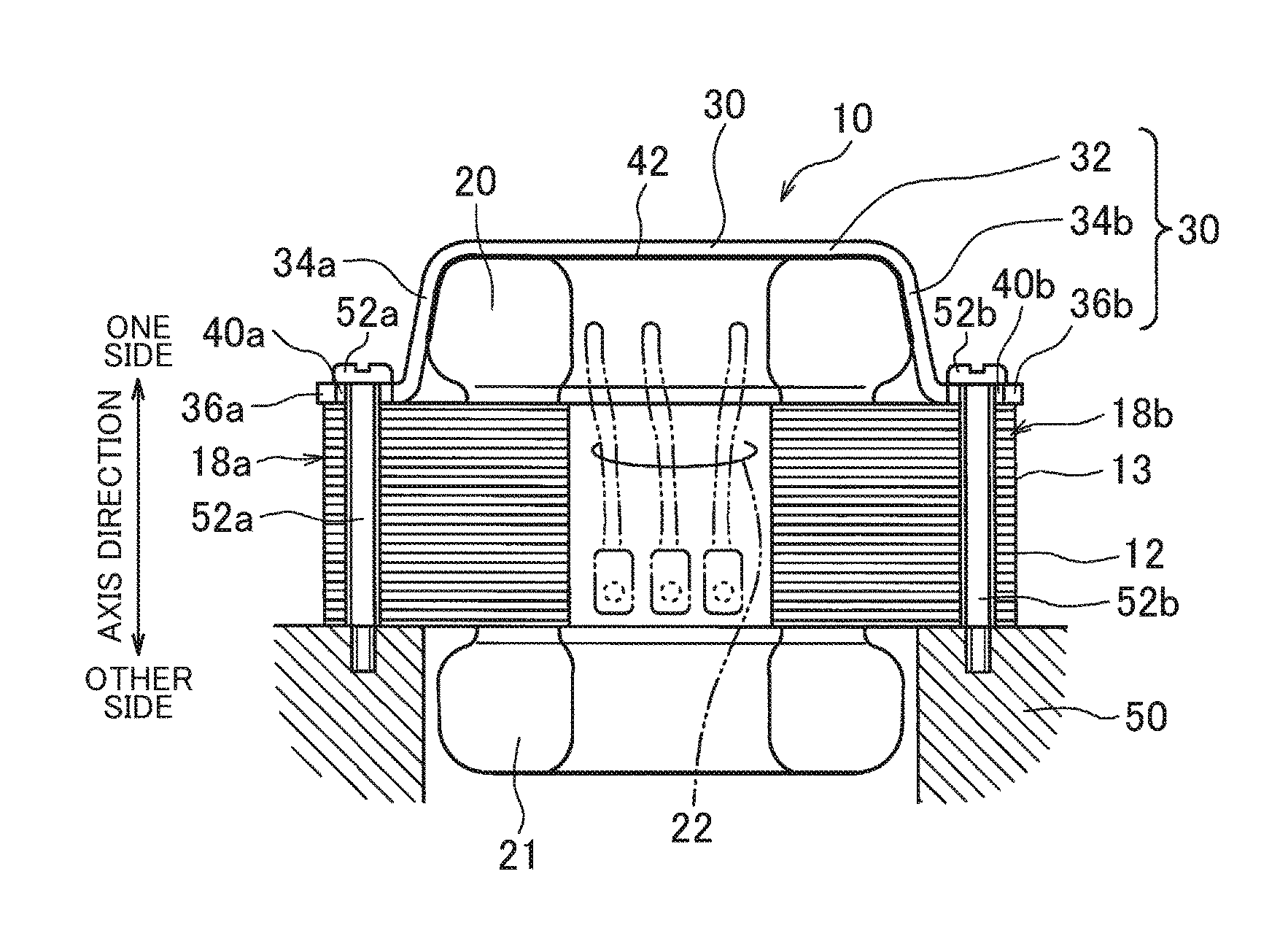
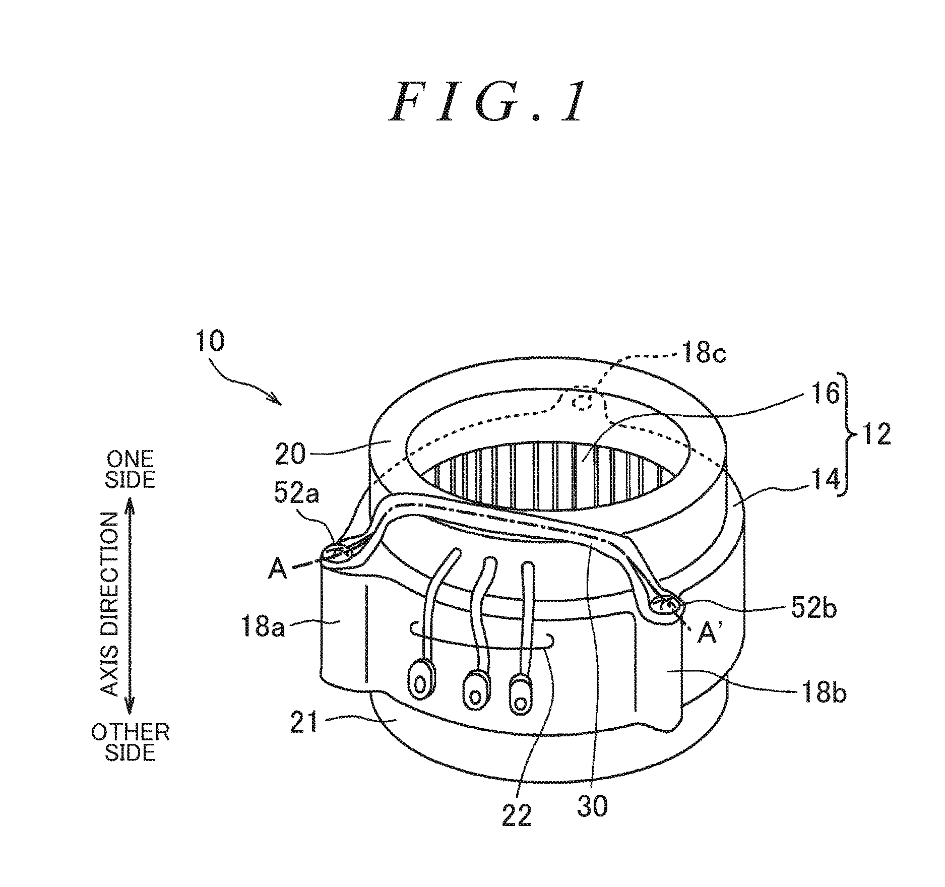
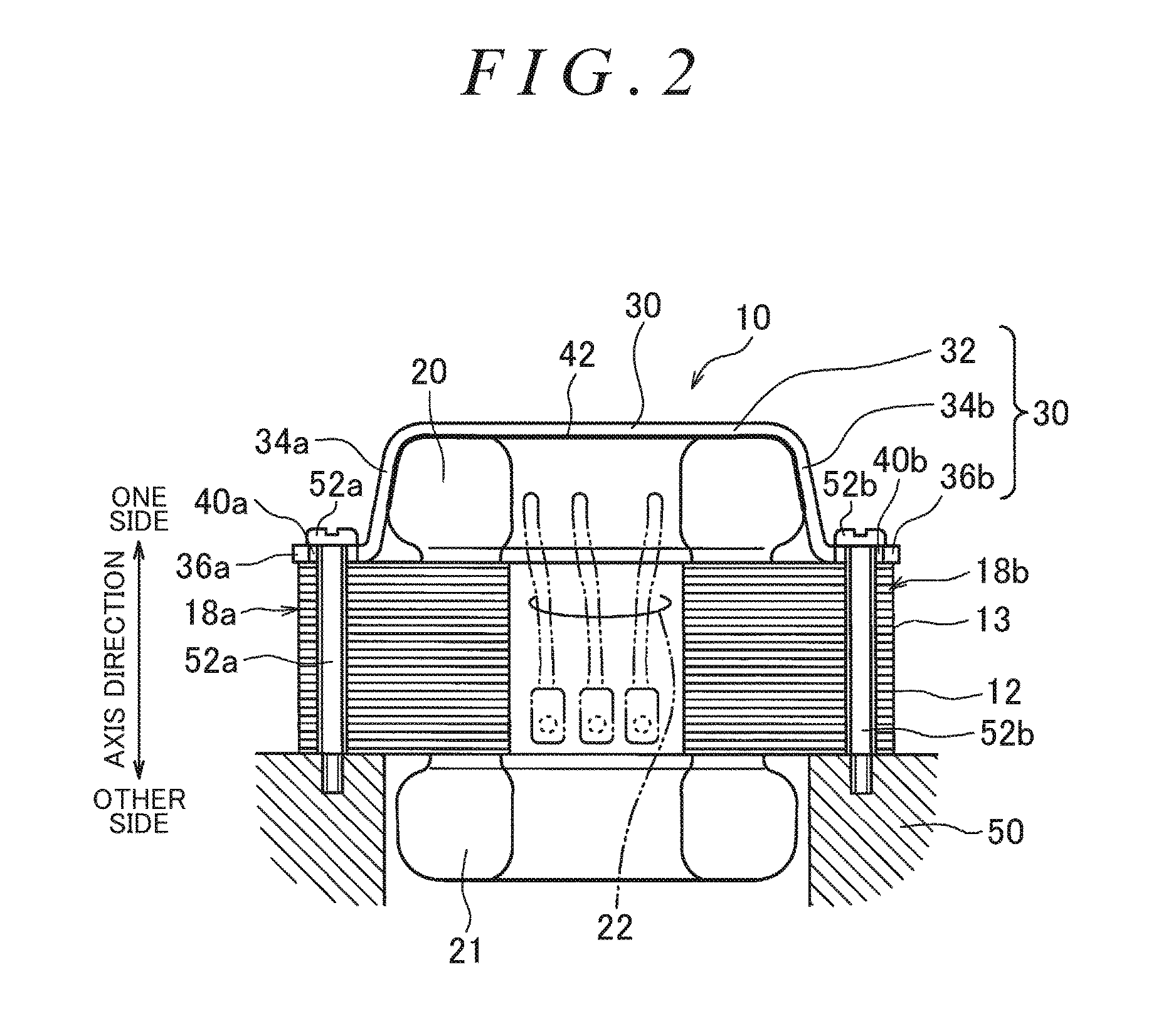
[0022]FIG. 1 is a perspective view of a rotary electric machine stator 10. In the below, unless otherwise mentioned, the rotary electric machine stator 10 is referred to as “stator 10”. A rotary electric machine using a ...


PUM


Abstract

A rotary electric machine stator includes a stator core including a plurality of teeth, a coil wound around the teeth, a power wire being drawn out from the coil, and a retainer member that presses the coil end against the stator core. The retainer member includes a pressing portion disposed on an end surface in an axis direction of the coil end, leg portions extending from respective end portions on opposite sides of the pressing portion toward respective attachment portions provided at the stator core, and attachment ends provided at the respective leg portions and fixed to the respective attachment portions, and the power wire is drawn out from between the leg portions on the opposite sides of the pressing portion.

Description

INCORPORATION BY REFERENCE[0001]The disclosure of Japanese Patent Application No. 2015-137791 filed on Jul. 9, 2015 including the specification, drawings and abstract is incorporated herein by reference in its entirety.BACKGROUND1. Technical Field[0002]The present disclosure relates to a rotary electric machine stator, and specifically relates to a rotary electric machine stator in which a power wire is drawn out from a coil end.2. Description of Related Art[0003]Japanese Patent Application Publication No. 2013-126329 discloses that insulation between a motor case and a bus bar module from which power wires are drawn out is ensured by an insulation cover covering the bus bar module, at a coil end of a rotary electric machine stator.[0004]Japanese Patent Application Publication No. 2013-074644 described that in a stator for a motor to be used in an electric vacuum cleaner, a part of an end portion in an axis direction of a resin retainer disposed on the inner peripheral side of a coi...

Claims


Application Information

Patent Timeline
IPC IPC(8): H02K3/52H02K5/22
CPCH02K5/225H02K3/522
Inventor YAMAGISHI, YOSHITADA
Owner TOYOTA JIDOSHA KK
Why Eureka
Try Eureka